Vol. 13
Latest Volume
All Volumes
PIERC 143 [2024] PIERC 142 [2024] PIERC 141 [2024] PIERC 140 [2024] PIERC 139 [2024] PIERC 138 [2023] PIERC 137 [2023] PIERC 136 [2023] PIERC 135 [2023] PIERC 134 [2023] PIERC 133 [2023] PIERC 132 [2023] PIERC 131 [2023] PIERC 130 [2023] PIERC 129 [2023] PIERC 128 [2023] PIERC 127 [2022] PIERC 126 [2022] PIERC 125 [2022] PIERC 124 [2022] PIERC 123 [2022] PIERC 122 [2022] PIERC 121 [2022] PIERC 120 [2022] PIERC 119 [2022] PIERC 118 [2022] PIERC 117 [2021] PIERC 116 [2021] PIERC 115 [2021] PIERC 114 [2021] PIERC 113 [2021] PIERC 112 [2021] PIERC 111 [2021] PIERC 110 [2021] PIERC 109 [2021] PIERC 108 [2021] PIERC 107 [2021] PIERC 106 [2020] PIERC 105 [2020] PIERC 104 [2020] PIERC 103 [2020] PIERC 102 [2020] PIERC 101 [2020] PIERC 100 [2020] PIERC 99 [2020] PIERC 98 [2020] PIERC 97 [2019] PIERC 96 [2019] PIERC 95 [2019] PIERC 94 [2019] PIERC 93 [2019] PIERC 92 [2019] PIERC 91 [2019] PIERC 90 [2019] PIERC 89 [2019] PIERC 88 [2018] PIERC 87 [2018] PIERC 86 [2018] PIERC 85 [2018] PIERC 84 [2018] PIERC 83 [2018] PIERC 82 [2018] PIERC 81 [2018] PIERC 80 [2018] PIERC 79 [2017] PIERC 78 [2017] PIERC 77 [2017] PIERC 76 [2017] PIERC 75 [2017] PIERC 74 [2017] PIERC 73 [2017] PIERC 72 [2017] PIERC 71 [2017] PIERC 70 [2016] PIERC 69 [2016] PIERC 68 [2016] PIERC 67 [2016] PIERC 66 [2016] PIERC 65 [2016] PIERC 64 [2016] PIERC 63 [2016] PIERC 62 [2016] PIERC 61 [2016] PIERC 60 [2015] PIERC 59 [2015] PIERC 58 [2015] PIERC 57 [2015] PIERC 56 [2015] PIERC 55 [2014] PIERC 54 [2014] PIERC 53 [2014] PIERC 52 [2014] PIERC 51 [2014] PIERC 50 [2014] PIERC 49 [2014] PIERC 48 [2014] PIERC 47 [2014] PIERC 46 [2014] PIERC 45 [2013] PIERC 44 [2013] PIERC 43 [2013] PIERC 42 [2013] PIERC 41 [2013] PIERC 40 [2013] PIERC 39 [2013] PIERC 38 [2013] PIERC 37 [2013] PIERC 36 [2013] PIERC 35 [2013] PIERC 34 [2013] PIERC 33 [2012] PIERC 32 [2012] PIERC 31 [2012] PIERC 30 [2012] PIERC 29 [2012] PIERC 28 [2012] PIERC 27 [2012] PIERC 26 [2012] PIERC 25 [2012] PIERC 24 [2011] PIERC 23 [2011] PIERC 22 [2011] PIERC 21 [2011] PIERC 20 [2011] PIERC 19 [2011] PIERC 18 [2011] PIERC 17 [2010] PIERC 16 [2010] PIERC 15 [2010] PIERC 14 [2010] PIERC 13 [2010] PIERC 12 [2010] PIERC 11 [2009] PIERC 10 [2009] PIERC 9 [2009] PIERC 8 [2009] PIERC 7 [2009] PIERC 6 [2009] PIERC 5 [2008] PIERC 4 [2008] PIERC 3 [2008] PIERC 2 [2008] PIERC 1 [2008]
2010-05-26
PIER C
Vol. 13, 245-257, 2010
download: 233
A Method to Design Dual-Band, High-Directivity EBG Resonator Antennas Using Single-Resonant, Single-Layer Partially Reflective Surfaces
Yuehe Ge , Karu P. Esselle and Trevor S. Bird
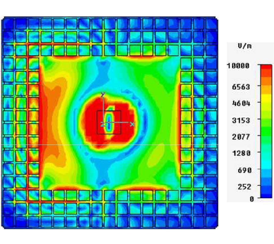
A new method is presented to design dual-band, high-directivity, EBG-resonator antennas using simple, single-resonant, single-layer partially reflective surfaces (PRS). The tailored abrupt reflection phase change of partially reflecting surfaces, observed only at the resonance frequency of the PRS resonant inclusions (such as dipoles and slots), is exploited for this purpose. An example single-resonant PRS, based on a frequency-selective surface (FSS) composed of a printed slot array, was designed. Then it is used to design an EBG-resonator antenna to demonstrate the feasibility of achieving dual-band performance. Cavity models are employed, together with the reflection characteristics of the PRS, to understand the operation of the device at critical frequencies such as cavity resonance frequencies and the PRS resonance frequency. Antenna simulations and computed results confirm the dual-band operation of this very simple, singlelayer, low-profile EBG-resonator antenna. It resonates in two bands centered at 10.5 GHz and 12.3 GHz. The peak directivity in each band is 18.2 dBi and 20.5 dBi, and the 3dB directivity bandwidth of each band is 7.5% and 8.7%, respectively.
A METHOD TO DESIGN DUAL-BAND, HIGH-DIRECTIVITY EBG RESONATOR ANTENNAS USING SINGLE-RESONANT, SINGLE-LAYER PARTIALLY REFLECTIVE SURFACES
2010-05-20
PIER C
Vol. 13, 231-243, 2010
download: 232
Utilizing Nonuniform Coupled Transmission Lines to Compact Microstrip Circuits Such as Edge-Coupled Bandpass Filters
Mohammad Khalaj-Amirhosseini and Ali H.Tehrani
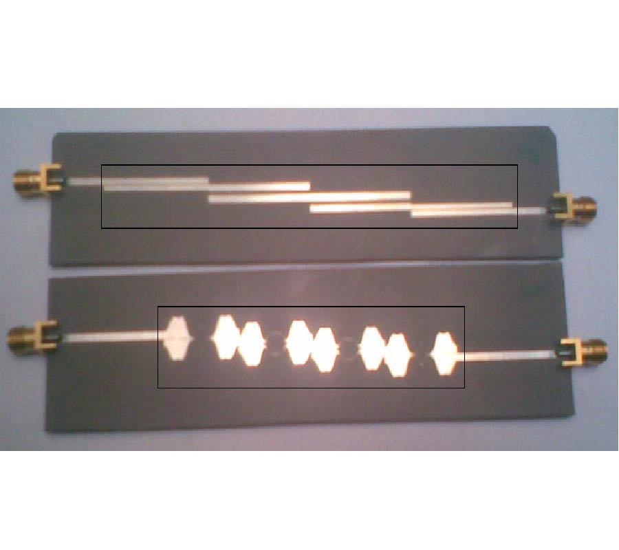
In this paper, we propose a method to reduce the length of the narrowband microstrip Uniform Coupled Transmission Lines (UCTLs), which has a general application to compact microstrip circuits. In this method, we use Nonuniform Coupled Transmission Lines (NCTLs) instead of UCTLs. To synthesize the desired NCTLs, their normalized width and gap are expanded as two truncated Fourier series. Then, the optimal values of the coefficients of the series are obtained through an optimization approach. The usefulness of the proposed method is verified using some examples. Also, an edged-coupled bandpass filter is compacted using the proposed method and then is fabricated and measured.
UTILIZING NONUNIFORM COUPLED TRANSMISSION LINES TO COMPACT MICROSTRIP CIRCUITS SUCH AS EDGE-COUPLED BANDPASS FILTERS
2010-05-14
PIER C
Vol. 13, 217-229, 2010
download: 732
High Impedance Surfaces Based Antennas for High Data Rate Communications at 40 GHz
Cuong-Manh Tran , Habiba Hafdallah-Ouslimani , Luyang Zhou , Alain C. Priou , Herve Teillet , Jean-Yves Daden and Abdelwaheb Ourir
Millimeter wave High Impedance Surfaces (HIS) based antennas are designed, fabricated, and characterized for high data rate communications at frequencies around 40 GHz. HIS with different finite surface area sizes are used as a ground plane for the microstrip patch antennas to suppress the surface waves. The antenna measurements and full wave electromagnetic simulations demonstrate a wide bandwidth of 12-15% in the frequency range of 38-44 GHz with a high gain of ~6 dB and a very low cross polar contribution better than -20 dB.
HIGH IMPEDANCE SURFACES BASED ANTENNAS FOR HIGH DATA RATE COMMUNICATIONS AT 40 GHz
2010-05-13
PIER C
Vol. 13, 203-216, 2010
download: 270
Development of Polymer-Based Dielectric Resonator Antennas for Millimeter-Wave Applications
Atabak Rashidian , David M. Klymyshyn , Mohammadreza Tayfeh Aligodarz , Martin Boerner and Juergen Mohr
The goal of this paper is to use polymer-based materials (instead of hard ceramics) in fabrication of dielectric resonator antennas at millimeter-wave frequencies. The soft nature of polymers facilitates machining of antennas, while the low permittivity of polymers naturally enhances the bandwidth. More importantly, advantageous properties (e.g., flexibility and photosensitivity) of some polymers introduce special capabilities which can not be achieved by ceramics. A photosensitive polymer is utilized in this paper to fabricate polymer-based resonator antennas. As a result, deep X-ray lithography is enabled to produce high quality antenna structures. The proposed dielectric resonator antennas which inherently have very low relative permittivity (usually in a range from 3 to 5) are excited effectively using a slotcoupled feeding method and analyzed in both the frequency and time domains. Impedance and radiation properties are compared with higher permittivity ceramic antennas. Impedance bandwidths up to 32 percent are measured and stable radiation patterns with low cross polarization levels over the entire bandwidth are achieved for the prototype antenna. This method enables lithography-based batch fabrication of structures with fine features and complex geometries.
DEVELOPMENT OF POLYMER-BASED DIELECTRIC RESONATOR ANTENNAS FOR MILLIMETER-WAVE APPLICATIONS
2010-05-11
PIER C
Vol. 13, 195-202, 2010
download: 234
Interaction of Medical Implants with the MRI Electromagnetic Fields
Syed Mohsin , John Nyenhuis and Rizwan Masood
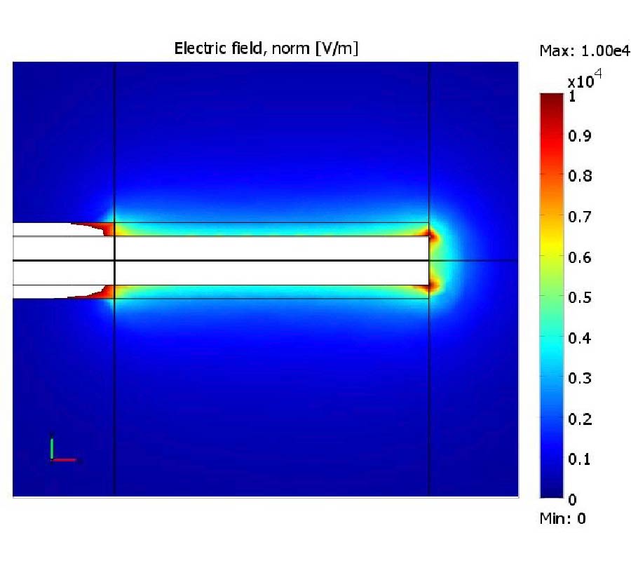
Medical implants in the form of linear conductive structures partially insulated along their length are especially prone to induced heating when subjected to the radiofrequency field used during magnetic resonance imaging (MRI). Leads or similar structures are often implanted near the skin and we have analyzed such implants when the implantation depth is varied in steps from 3 mm to 9 mm or more. Current, electric field, and induced temperature rise distributions in tissue have been obtained. The results have been validated by laboratory measurements.
INTERACTION OF MEDICAL IMPLANTS WITH THE MRI ELECTROMAGNETIC FIELDS
2010-05-06
PIER C
Vol. 13, 187-193, 2010
download: 204
A Simple Method to Design a Compact and High Performance Dual-Band Bandpass Filter for GSM and WLAN
Cheng-Yuan Hung , Ru-Yuan Yang and Yueh-Ling Lin
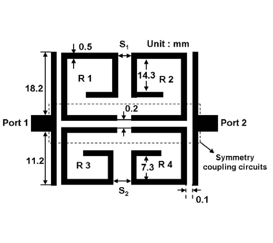
This paper proposes a novel compact dual-band bandpass filter (BPF) using four spiral resonators for application in GSM and IEEE 802.11b WLANs for the first time. Since the two passbands can be tuned individually, the filter has more design freedoms. The symmetry coupling structure is realized to achieve a isolation higher than 30 dB between the lower and higher passbands. The full-wave simulator IE3D is used to design the spiral resonators and calculate the coupling coefficients of the basic coupling structures. The designed BPF is fabricated and measured. Good agreement between the simulated and measured results verifies our design concept.
A SIMPLE METHOD TO DESIGN A COMPACT AND HIGH PERFORMANCE DUAL-BAND BANDPASS FILTER FOR GSM AND WLAN
2010-05-05
PIER C
Vol. 13, 171-185, 2010
download: 365
On the Optimal Design of Multilayer Microwave Absorbers
Nihad I. Dib , Mujahed Asi and Ayman Sabbah
In this paper, some common misconceptions in several papers dealing with the optimal design of multilayer microwave absorbers are indicated. Specifically, it is emphasized that Chew's recursive formula for the reflection coefficient of multilayer media for the TM polarization corresponds to the magnetic field, not the electric field. It is also emphasized that both TM and TE polarizations should have the same magnitude of the reflection coefficient for the case of normal incidence. Numerical optimal results are also presented and ompared with those existing in the literature.
ON THE OPTIMAL DESIGN OF MULTILAYER MICROWAVE ABSORBERS
2010-04-28
PIER C
Vol. 13, 159-170, 2010
download: 195
A Compact CPW-Fed UWB Slot Antenna with Cross Tuning Stub
Johnson William and Rangaswamy Nakkeeran
Design and analysis of a compact coplanar waveguide (CPW) fed Ultra Wideband (UWB) slot antenna is presented in this paper. The antenna consists of a rectangular slot with cross like structure at the anterior portion of the feed which acts as tuning stub. The CPW feed is designed for 50 ­Ω impedance. The physical dimension of the proposed antenna is 19 mm (length)×20 mm (width)×1.6 mm (thickness), and the electrical size is 0.3 λl (length)×0.32 λl (width)(fl=4.8 GHz). The characteristics of the designed structure are investigated by using MoM based electromagnetic solver, IE3D. An extensive analysis of the proposed antenna in the frequency and time domains are presented. The antenna was fabricated with FR4 substrate and characterized by measuring returnloss, radiation pattern (5.5 GHz) and gain. The measured results are appreciably in good agreement with the simulated ones. A better impedance bandwidth is obtained from 4.8 GHz to 12.8 GHz that constitutes a fractional bandwidth of 90% with return loss less than or equal to -10 dB (VSWR < 2). Time domain analysis of the antenna is also performed, which witnessed the linear phase and less distortion. The simple configuration and low profile nature of the proposed antenna leads to easy fabrication that may be built for any wireless UWB device applications.
A COMPACT CPW-FED UWB SLOT ANTENNA WITH CROSS TUNING STUB
2010-04-27
PIER C
Vol. 13, 149-158, 2010
download: 215
Small Semi-Circle-Like Slot Antenna for Ultra-Wideband Applications
Farooq Amini , Mohammad Naghi Azarmanesh and Mouhammad Ojaroudi
In this paper, a small modified circle-like slot antenna with modified radiating patch, for UWB applications is proposed. The proposed antenna consists of a modified radiating patch with novel notch and a semi-circle-like with a slope which provides a wide usable fractional bandwidth of more than 135% (3.07-16.26 GHz). By optimizing the notched radiating patch, the total bandwidth of the antenna is greatly improved. The designed antenna has a small size of 27.5×27.5 mm2.
SMALL SEMI-CIRCLE-LIKE SLOT ANTENNA FOR ULTRA-WIDEBAND APPLICATIONS
2010-04-26
PIER C
Vol. 13, 135-148, 2010
download: 261
On-Chip Fgcpw Lowpass and Bandpass Filters with Low Insertion Loss and High Stopband Rejection for V-Band Applications
Hwann-Kaeo Chiou and I-Shan Chen
This paper presents compact on-chip finite ground coplanar waveguide (FGCPW) lowpass filter (LPF) and bandpass filter (BPF) for V-band multi gigabit per second (Gbps) wireless personal area network (WPAN) applications. The equivalent lumped-element circuit of the proposed filters can be represented by an ABCD matrix which is obtained by consecutively multiplied ABCD matrixes of one T-network impedance and two shunt admittances. The full-wave EM simulators, AnsoftTM HFSS and AgilentTM Momentum, were used to fine tune the desired frequency response. The FGCPW LPF and BPF were implemented in WINTM semiconductor 0.15 μm pHEMT process. The obtained insertion losses are smaller than 0.5 dB and 1.5 dB with return losses of better than 20 dB and 13 dB, respectively. The 1-dB bandwidths of the LPF and BPF are 70 GHz (0-70 GHz) and 11 GHz (55-66 GHz), respectively. The stopband rejections are better than 20 dB from 95 to 120 GHz in the LPF, and from 0 to 42 GHz and 82 to 120 GHz in the BPF. The measured frequency responses show good agreements with the simulations. The chip size is very compact of 0.43×0.45 mm2.
ON-CHIP FGCPW LOWPASS AND BANDPASS FILTERS WITH LOW INSERTION LOSS AND HIGH STOPBAND REJECTION FOR V-BAND APPLICATIONS
2010-04-26
PIER C
Vol. 13, 121-134, 2010
download: 223
A Broadband Dual-Inflection Point RF Predistortion Linearizer Using Backward Reflection Topology
Mohammad S. Hashmi , Zaharia S. Rogojan , S. R. Nazifi and Fadhel M. Ghannouchi
This paper presents a flexible and generic broadband RF predistortion linearizer designed using backward reflection topology that can correct for the dualinflection point type compression characteristics usually encountered in the gain profile of metal semiconductor field effect transistor (MESFET) based power amplifiers. It employs circuit configuration of two parallel Schottky diodes with one p-intrinsic-n (PIN) diode in parallel, connected at two ports of a 90°hybrid coupler. The Schottky diodes are coupled via a quarter wave transmission line segment which generates dual inflection points in the gain characteristics of the linearizer. The incorporation of a PIN diode helps in improving the achievable range in the gain and phase characteristics of the linearizer. Overall, the linearizer is capable of linearizing various types of power amplifiers owing to the flexible control on the linearizer's parameters and eventually the gain and phase characteristics of the linearizer. The proposed linearizer can be employed in the frequency range of 1.4-2.8 GHz and can simultaneously improve the third- and fifth-order intermodulation distortions. The measurements carried out on a commercial ZHL-4240 gallium arsenide field effect transistor (GaAs FET) based power amplifier demonstrates the broadband functionality of the proposed linearizer.
A BROADBAND DUAL-INFLECTION POINT RF PREDISTORTION LINEARIZER USING BACKWARD REFLECTION TOPOLOGY
2010-04-23
PIER C
Vol. 13, 107-119, 2010
download: 196
A Reconfigurable Active Array Antenna System with the Frequency Reconfigurable Amplifiers Based on RF MEMS Switches
Seong-Sik Myoung , Jong-Gwan Yook , Soon Young Eom , Soon-Ik Jeon , Terence Wu , Rong-Lin Li , Kyutae Lim , Manos M. Tentzeris and Joy Laskar
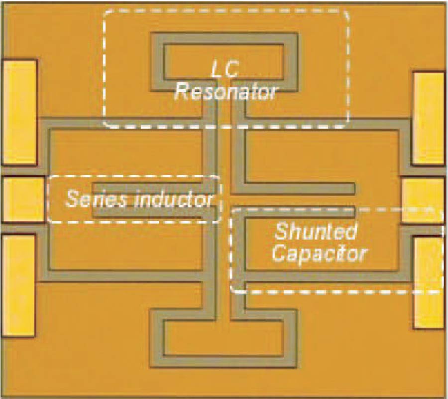
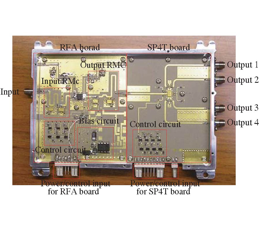
In this paper, a frequency reconfigurable active array antenna (RAA) system, which can be reconfigurable at three different frequency bands, is proposed. The proposed RAA system is designed with a novel frequency reconfigurable front-end amplifiers (RFA) designed with the simple reconfigurable impedance matching circuits (RMC) with the MEMS switches. With the MEMS switch, the RFA is realized without any performance sacrifice especially linear characteristic. The proposed RMC is composed of a series transmission line and a shunt capacitor, and an arbitrary impedance can be transformed to any other impedance value with single switch control for a desired frequency band. The proposed RAA antenna system is composed of the RMC, RFA with the RMC, 2×2 array of reconfigurable antenna elements (RAE), as well as a reconfiguration control board (RCB) for MEMS switch control, and the validity of the proposed RMC, RFA, as well as RAA system, which is presented with the experimental results.
A RECONFIGURABLE ACTIVE ARRAY ANTENNA SYSTEM WITH THE FREQUENCY RECONFIGURABLE AMPLIFIERS BASED ON RF MEMS SWITCHES
2010-04-21
PIER C
Vol. 13, 91-106, 2010
download: 273
Optimization of Hata Propagation Prediction Model in Suburban Area in Malaysia
Mardeni Bin Roslee and Kok Foong Kwan
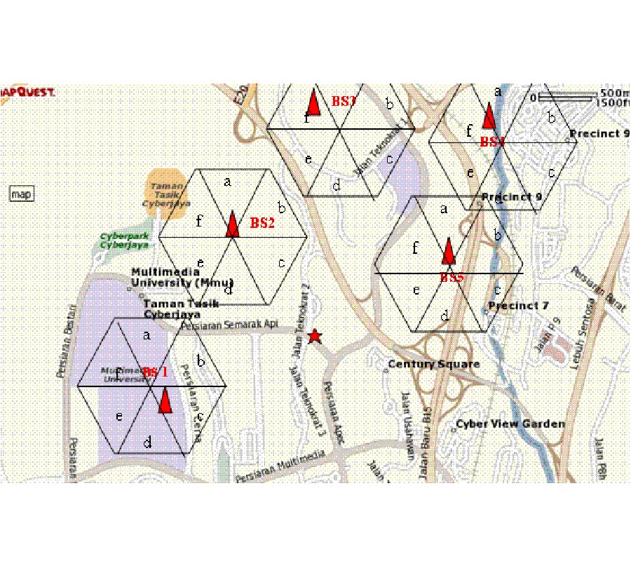
This paper describes a study on RF attenuation path loss behavior in suburban coverage within Cyberjaya and Putrajaya areas, located in Selangor State in Malaysia. The objective of this study is to develop and optimize a path loss model based on the existing Hata path loss model and outdoor measurement using frequency range from 400 MHz to 1800 MHz. The optimized model had been used and validated at places within Putrajaya area to find the relative error in order to assess its performance. The values for modified empirical parameters of Hata model were developed and presented in this paper. From the simulation result, the optimized model is found to best fit into the base station located at Putrajaya with smaller mean relative error. The smaller mean error shows that the optimization has been done successfully and thus, this optimized model can be useful to telecommunication providers in Malaysia in order to improve their service for mobile user satisfaction.
OPTIMIZATION OF HATA PROPAGATION PREDICTION MODEL IN SUBURBAN AREA IN MALAYSIA
2010-04-15
PIER C
Vol. 13, 77-90, 2010
download: 345
Improving Frequency Response of Microstrip Filters Using Defected Ground and Defected Microstrip Structures
Jose Alfredo Tirado-Mendez , Hildeberto Jardon-Aguilar , Ruben Flores-Leal , Edgar Andrade-Gonzalez and Flavio Iturbide-Sanchez
In this work, the introduction of Defected Microstrip Structures and Defected Ground Structures is presented to improve the performance of a traditional stepped-impedance microstrip lowpass filter. The attenuation in the stop-band is enhanced by more than 15 dB and selectivity is increased, without modifying the insertion loss in the pass band. A comparison of characteristics in filters is made when the combination of Defected Ground and Defected Microstrip Structures, as well as when only the first one are used. A model of the Defected Microstrip Structure and the corresponding equations to obtain the equivalent lumped and distributed element values are also given.
IMPROVING FREQUENCY RESPONSE OF MICROSTRIP FILTERS USING DEFECTED GROUND AND DEFECTED MICROSTRIP STRUCTURES
2010-04-13
PIER C
Vol. 13, 67-76, 2010
download: 283
Material-Loaded High q -Factor Slot Resonator and Measurement of Relative Permittivity
Adel B. Abdel-Rahman , Mohamed Kheir , Anand Kumar Verma and Abbas Omar
We introduce a new slot resonator in the ground plane of a microstrip that is loaded with a parallel plate capacitor. The loaded slot has a 73% reduced length. Its unloaded Q-factor is 98 which is 91% higher than that of an ordinary slot. It is suitable to reject the narrow band unwanted signal. The proposed high Q-factor compact slot resonator also suppresses the undesired spurious high frequency response of the unloaded slot resonator. The structure is further used to determine the unknown dielectric constant of a sheet material with 0.04 variation in εr.
MATERIAL-LOADED HIGH Q-FACTOR SLOT RESONATOR AND MEASUREMENT OF RELATIVE PERMITTIVITY
2010-04-13
PIER C
Vol. 13, 51-66, 2010
download: 213
Application of Complete Complementary Sequence in Orthogonal MIMO SAR System
Shufeng Li , Jie Chen , Lvqian Zhang and Yin-Qing Zhou
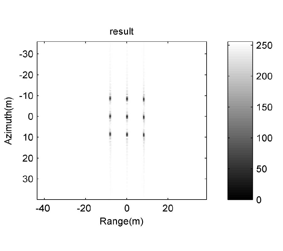
The Complete Complementary Sequence (CC-S) consists of several complementary orthogonal sequences and has optimal sidelobe level performance, which is satisfied with the requirement of the orthogonal Multiple Input Multiple Output (MIMO) radar signals. Aimed at the difficulty of high sidelobe level in Synthetic Aperture Radar (SAR) imaging processing in range dimension, an approach of depressing sidelobe level based on CC-S in MIMO SAR system was proposed. The transmitter model for orthogonal MIMO SAR system using CC-S and the corresponding matched filter (MF) were established in this paper. In addition, the MIMO SAR imaging results were simulated. The simulation results demonstrate that the performance of CC-S employed in orthogonal MIMO radar system is much better than that with traditional Linear Frequency Modulation (LFM) signal, by which the feasibility and validity of CC-S applied in orthogonal MIMO SAR system are justified.
APPLICATION OF COMPLETE COMPLEMENTARY SEQUENCE IN ORTHOGONAL MIMO SAR SYSTEM
2010-04-12
PIER C
Vol. 13, 41-50, 2010
download: 196
Wave Analysis for Inductively Matched Millimeter Wave Amplifier Design
Mahmoud Mohammad-Taheri , Mehrdad Fahimnia , Ying Wang , Ming Yu and Safieddin Safavi-Naeini
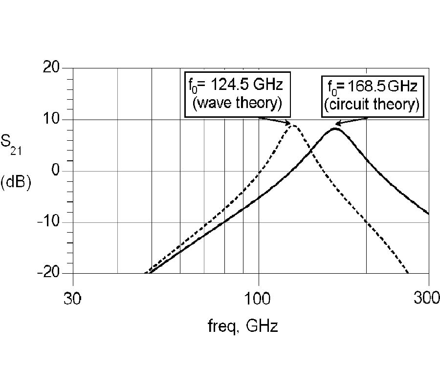
A new design approach based on wave analysis has been implemented in order to derive voltage gain, center frequency and bandwidth of millimeter wave amplifier using parameters of transmission lines (TL). The derived formula allows one to design high frequency amplifier with predetermined bandwidth and centner frequency. It has been shown that in the case of lossy TL or at high frequency, circuit theory cannot predict the amplifier gain behavior while presented wave theory can accurately predict the frequency response of the amplifier in both low and high frequency ranges.
WAVE ANALYSIS FOR INDUCTIVELY MATCHED MILLIMETER WAVE AMPLIFIER DESIGN
2010-04-07
PIER C
Vol. 13, 33-40, 2010
download: 242
Realization of a Compact Branch-Line Coupler Using Quasi-Fractal Loaded Coupled Transmission-Lines
Mehdi Nosrati and Bal Singh Virdee
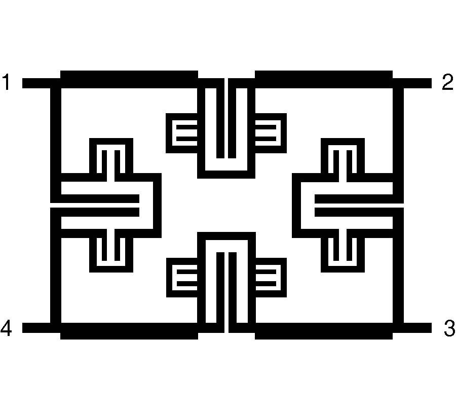
An extremely compact branch-line coupler operating at 900 MHz is presented without the use of viaholes, multilayered technique, or air-bridged. The technique presented here uses the concept of fractals to load a coupled transmission-line in order to realize a compact quarter-wavelength transmission-line, which forms the couplers arms. It is shown that the proposed branch-line coupler's performance is analogous to a conventional branch-line coupler with the benefit of substantially reduced physical dimensions by a factor of 78%. The measured result of the fabricated microstrip branch-line coupler is compared with the simulation data. The agreement of the measurement and simulated confirms the theory and validates the proposed coupler design.
REALIZATION OF A COMPACT BRANCH-LINE COUPLER USING QUASI-FRACTAL LOADED COUPLED TRANSMISSION-LINES
2010-04-07
PIER C
Vol. 13, 19-32, 2010
download: 340
Effects of DC-Bias Conditions on Low-Loss Thin Film Microstrip Line
Hung-Wei Wu and Min-Hang Weng
This paper presents the microwave characteristics of thin film microstrip line (TFML) under dc-bias conditions. The proposed TFML with 20 μm thick polyimide layer is used as a thin dielectric supporter on low-resistivity silicon (LRS) substrate. Measured frequency-dependent microwave characteristics and equivalent lumped elements are evaluated for the dc-biased TFML over 1-50 GHz. This work presents acceptable attenuation of 0.561, 0.563 and 0.565 dB/mm at 50 GHz with dc-bias conditions, showing that the TFML can be used for high frequency interconnects for any 3D-based microwave devices and monolithic microwave integrated circuits (MMICs).
EFFECTS OF DC-BIAS CONDITIONS ON LOW-LOSS THIN FILM MICROSTRIP LINE
2010-04-05
PIER C
Vol. 13, 1-18, 2010
download: 265
A Flexible Dual-Inflection Point RF Predistortion Linearizer for Microwave Power Amplifiers
Mohammad S. Hashmi , Zaharia S. Rogojan and Fadhel M. Ghannouchi
This paper presents a very flexible and generic design of a diode-based RF predistortion linearizer that can correct for the dual-inflection point type compression characteristics found in the gain profile of metal semiconductor field effect transistor (MESFET) based and Doherty power amplifiers. It consists of a circuit configuration that has the head-tail configuration of Schottky diodes, complemented with a p-intrinsic-n (PIN) diode in parallel, at two ports of a 90° hybrid coupler for improving the performance of the linearizer. The use of a PIN diode in the linearizer provides it with an extra level of freedom in achieving the desired characteristic. Overall, the linearizer is equipped with three degrees of freedom and hence possesses the capability to achieve output characteristics that can be employed in linearizing various types of power amplifiers. The proposed linearizer has been shown to simultaneously improve the third- and fifth-order intermodulation distortions of a commercial ZHL-4240 gallium arsenide field effect transistor (GaAs FET) based power amplifier over a 10 dB power range.
A FLEXIBLE DUAL-INFLECTION POINT RF PREDISTORTION LINEARIZER FOR MICROWAVE POWER AMPLIFIERS