Vol. 19
Latest Volume
All Volumes
PIERC 143 [2024] PIERC 142 [2024] PIERC 141 [2024] PIERC 140 [2024] PIERC 139 [2024] PIERC 138 [2023] PIERC 137 [2023] PIERC 136 [2023] PIERC 135 [2023] PIERC 134 [2023] PIERC 133 [2023] PIERC 132 [2023] PIERC 131 [2023] PIERC 130 [2023] PIERC 129 [2023] PIERC 128 [2023] PIERC 127 [2022] PIERC 126 [2022] PIERC 125 [2022] PIERC 124 [2022] PIERC 123 [2022] PIERC 122 [2022] PIERC 121 [2022] PIERC 120 [2022] PIERC 119 [2022] PIERC 118 [2022] PIERC 117 [2021] PIERC 116 [2021] PIERC 115 [2021] PIERC 114 [2021] PIERC 113 [2021] PIERC 112 [2021] PIERC 111 [2021] PIERC 110 [2021] PIERC 109 [2021] PIERC 108 [2021] PIERC 107 [2021] PIERC 106 [2020] PIERC 105 [2020] PIERC 104 [2020] PIERC 103 [2020] PIERC 102 [2020] PIERC 101 [2020] PIERC 100 [2020] PIERC 99 [2020] PIERC 98 [2020] PIERC 97 [2019] PIERC 96 [2019] PIERC 95 [2019] PIERC 94 [2019] PIERC 93 [2019] PIERC 92 [2019] PIERC 91 [2019] PIERC 90 [2019] PIERC 89 [2019] PIERC 88 [2018] PIERC 87 [2018] PIERC 86 [2018] PIERC 85 [2018] PIERC 84 [2018] PIERC 83 [2018] PIERC 82 [2018] PIERC 81 [2018] PIERC 80 [2018] PIERC 79 [2017] PIERC 78 [2017] PIERC 77 [2017] PIERC 76 [2017] PIERC 75 [2017] PIERC 74 [2017] PIERC 73 [2017] PIERC 72 [2017] PIERC 71 [2017] PIERC 70 [2016] PIERC 69 [2016] PIERC 68 [2016] PIERC 67 [2016] PIERC 66 [2016] PIERC 65 [2016] PIERC 64 [2016] PIERC 63 [2016] PIERC 62 [2016] PIERC 61 [2016] PIERC 60 [2015] PIERC 59 [2015] PIERC 58 [2015] PIERC 57 [2015] PIERC 56 [2015] PIERC 55 [2014] PIERC 54 [2014] PIERC 53 [2014] PIERC 52 [2014] PIERC 51 [2014] PIERC 50 [2014] PIERC 49 [2014] PIERC 48 [2014] PIERC 47 [2014] PIERC 46 [2014] PIERC 45 [2013] PIERC 44 [2013] PIERC 43 [2013] PIERC 42 [2013] PIERC 41 [2013] PIERC 40 [2013] PIERC 39 [2013] PIERC 38 [2013] PIERC 37 [2013] PIERC 36 [2013] PIERC 35 [2013] PIERC 34 [2013] PIERC 33 [2012] PIERC 32 [2012] PIERC 31 [2012] PIERC 30 [2012] PIERC 29 [2012] PIERC 28 [2012] PIERC 27 [2012] PIERC 26 [2012] PIERC 25 [2012] PIERC 24 [2011] PIERC 23 [2011] PIERC 22 [2011] PIERC 21 [2011] PIERC 20 [2011] PIERC 19 [2011] PIERC 18 [2011] PIERC 17 [2010] PIERC 16 [2010] PIERC 15 [2010] PIERC 14 [2010] PIERC 13 [2010] PIERC 12 [2010] PIERC 11 [2009] PIERC 10 [2009] PIERC 9 [2009] PIERC 8 [2009] PIERC 7 [2009] PIERC 6 [2009] PIERC 5 [2008] PIERC 4 [2008] PIERC 3 [2008] PIERC 2 [2008] PIERC 1 [2008]
2011-02-22
PIER C
Vol. 19, 245-257, 2011
download: 420
UWB-MIMO Antenna with Novel Stub Structure
Ali Imram Najam , Yvan Duroc and Smail Tedjini
A compact printed and planar Multiple-Input Multiple-Output (MIMO) for Ultra Wideband (UWB) communications is presented. Two circular disc monopole antenna elements constitute the proposed UWB-MIMO antenna operating over the frequency band of 3.2-10.6 GHz. The isolation between the antenna ports has been enhanced to the value of more than 15 dB throughout the frequency band of interest. This enhancement is achieved by taking the advantage of an inverted-Y shaped stub that is being inserted on the ground plane of UWB-MIMO antenna. The insertion of the stub has also facilitated reduction of the size of the antenna, i.e., overall dimensions of the antenna are 40×68mm2. The proposed antenna is investigated both numerically and experimentally.
UWB-MIMO ANTENNA WITH NOVEL STUB STRUCTURE
2011-02-16
PIER C
Vol. 19, 235-243, 2011
download: 252
Compact Open-Ended L-Shaped Slot Antenna with Asymmetrical Rectangular Patch for UWB Applications
Kun Song , Ying-Zeng Yin , Shou-Tao Fan and Bo Chen
A novel compact open-ended L-shaped slot antenna with asymmetrical rectangular patch is demonstrated and designed for UWB applications. With the open-ended L-shaped slot and an asymmetrical rectangular patch fed by the micro-strip line, multiple resonant frequencies are excited and merged to form a measured widen operating bandwidth of 3.01~11.30 GHz with 10 dB return loss. The fractional bandwidth can be enhanced from previous 32% (3~4.15 GHz) to 112% (3~10.66 GHz) among three different antenna types in simulations. The details and vital parameters of the proposed slot antenna are also illustrated. In addition, the proposed slot antenna exhibits a small size of 22×25 mm2, which makes it an excellent candidate for UWB systems and portable applications.
COMPACT OPEN-ENDED L-SHAPED SLOT ANTENNA WITH ASYMMETRICAL RECTANGULAR PATCH FOR UWB APPLICATIONS
2011-02-10
PIER C
Vol. 19, 223-234, 2011
download: 213
An Ultra-Wideband Antenna with Band Reject Capability and Its Characterization in Time Domain
Rishik Bazaz , Shiban Kishen Koul , Mithilesh Kumar and Ananjan Basu
In this paper a square monopole antenna has been proposed which can be used for Ultra Wideband applications. Band-notch performance is introduced by an E-shaped slot on the patch. The dimensions are optimized to give not only the usual 3-10 GHz bandwidth with rejection in the 5-6 GHz band which is commonly used for WLAN, but also short received pulse duration when transmitted and received using a pair of these antennas. The demonstration of short received pulse-width is the primary novelty reported. The performance is verified by time domain measurements, in addition to the usual antenna characterization.
AN ULTRA-WIDEBAND ANTENNA WITH BAND REJECT CAPABILITY AND ITS CHARACTERIZATION IN TIME DOMAIN
2011-02-10
PIER C
Vol. 19, 207-222, 2011
download: 229
FPGA Based Realization of Aic for Applying CS to Radar
Xiuwei Chen , Yunhua Zhang and Xiangkun Zhang
Research on digital modeling and realization of non-correlation measurement frame for compressive sensing (CS) is conducted aiming at applying CS to imaging radar. FPGA based Analogue-to-Information Converter (AIC) is proposed and implemented. Real measurement data from AIC hardware platform and simulation data from AIC software platform are compressed to get range profiles, and the results agree well with what expected. The results show that the noise and synchronization error in real system deteriorate the performance of AIC thus CS remarkably.
FPGA BASED REALIZATION OF AIC FOR APPLYING CS TO RADAR
2011-02-03
PIER C
Vol. 19, 191-205, 2011
download: 238
External and Internal Electromagnetic Exposures of Workers Near High Voltage Power Lines
Nabil M. Maalej and C. Belhadj
The major objective of the study was to assess the safety of electric line workers exposed to of a double circuit 132 kV transmission line for different scenarios. The double circuit 132-kV, 60 Hz transmission line has a power rating of 293 MVA and a maximum recorded peak load current of 603 A. The charge simulation and the Biot Savart methods were used by EPRI workstation software to compute the external electric and magnetic fields around a 132 KV transmission line. We used the calculated external electric and magnetic field exposures to determine the induced electric field and induced current densities inside the human body. This was performed using the Finite Difference Time Difference computational algorithm in EMPIRE commercial software, with a 6 mm voxel resolution. We used the Visible Human (VH) to investigate the internal induced electric field and circulating current densities in more than 40 different tissues and organs of the VH. We found that the worker exposure levels to extremely low frequency electromagnetic fields are below the recommended IEEE international standards limits for the studied scenarios. In all scenarios the maximum induced current densities and electric fields were in the bone marrow of the feet.
EXTERNAL AND INTERNAL ELECTROMAGNETIC EXPOSURES OF WORKERS NEAR HIGH VOLTAGE POWER LINES
2011-01-28
PIER C
Vol. 19, 179-189, 2011
download: 317
Bandwidth Enhancement and Miniaturization of Dielectric Resonator Antenna for 5.8 GHz WLAN
K. K. Gebril , Sharul Kamal Bin Abd Rahim and Amuda Yusuf Abdulrahman
This paper presents the design of Dielectric Resonator Antenna (DRA) operating at 5.8 GHz, using the techniques of Two Segments DRA (TSDRA) and High-Aspect Ratio Structure. The aim of the paper is to reduce the size of the DRA while still maintaining its large impedance bandwidth. The requirements for WLAN applications are carefully taken into considerations in the design of the proposed structure. Comparison has been made between the proposed design and single layer DRA (SLDRA); and it has been found that former has better performances than the later.
BANDWIDTH ENHANCEMENT AND MINIATURIZATION OF DIELECTRIC RESONATOR ANTENNA FOR 5.8 GHZ WLAN
2011-01-27
PIER C
Vol. 19, 163-177, 2011
download: 124
Enclosure Effect on Microwave Power Amplifier
Jolly Dhar , Raj Kumar Arora , A. Dasgupta and S. S. Rana
The package design for microwave sub-systems requires adequate knowledge of electromagnetic field distribution inside the package housing. The cavity resonance of the microwave amplifier not only degrades the electrical performance, the feedback through the resonance mode also can cause unwanted oscillation in the frequency band of interest. It may even result in catastrophic failure of the device, wherein the peak oscillating voltage exceeds the device breakdown voltage. Hence, comprehensive analysis of the package effects is one of the prime requirements for stable microwave amplifier design for high-rel applications. This paper describes modeling, analysis of the package and different mitigation techniques to make stable, resonance free microwave amplifier for a C-band spaceborne SAR payload.
ENCLOSURE EFFECT ON MICROWAVE POWER AMPLIFIER
2011-01-27
PIER C
Vol. 19, 149-162, 2011
download: 244
A Novel 10 GHz Super-Heterodyne Bio-Radar System Based on a Frequency Multiplier and Phase-Locked Loop
Seong-Sik Myoung , Yong-Jun An , Jong-Gwan Yook , Byung-Jun Jang and Jun-Ho Moon
This paper presents a novel 10 GHz bio-radar system based on a frequency multiplier and phase-locked loop (PLL) for non-contact measurement of heartbeat and respiration rates. In this paper, a 2.5 GHz voltage controlled oscillator (VCO) with PLL is employed as a frequency synthesizer, and 10 GHz continuous wave (CW) signal is generated by using frequency multiplier from 2.5 GHz signal. This paper also presents the noise characteristics of the proposed system, and the analysis result shows that the same signal-to-noise-ratio (SNR) performance can be achieved with the proposed system based on the frequency multiplier compared with the conventional system with identical carrier frequency. The experimental results shows excellent vital-signal measurement up to 100 cm without any additional digital signal processing (DSP), thus proving the validity of the proposed system.
A NOVEL 10 GHZ SUPER-HETERODYNE BIO-RADAR SYSTEM BASED ON A FREQUENCY MULTIPLIER AND PHASE-LOCKED LOOP
2011-01-23
PIER C
Vol. 19, 135-147, 2011
download: 394
Development of a Wideband Highly Efficient GaN Vmcd VHF/UHF Power Amplifier
Song Lin and Aly Fathy
A 50 to 550 MHz wideband gallium nitride (GaN) HEMT power amplifier with over 43 dBm output power and 63% drain efficiency has been successfully developed. The demonstrated wideband power amplifier utilizes two GaN HEMTs and operates in a push-pull voltage mode Class D (VMCD). The design is based on a large signal simulation to optimize the power amplifier's output power and efficiency. To assure a wideband operation, a coaxial line impedance transformer has been used as part of the input matching network; meanwhile, a wideband a 1:1 ferrite loaded balun and low pass filters are utilized on the amplifier's output side instead of the conventional serial harmonic termination.
DEVELOPMENT OF A WIDEBAND HIGHLY EFFICIENT GAN VMCD VHF/UHF POWER AMPLIFIER
2011-01-18
PIER C
Vol. 19, 119-133, 2011
download: 373
Development of Circularly Polarized Array Antenna for Synthetic Aperture Radar Sensor Installed on UAV
Yohandri , Victor Wissan , I. Firmansyah , Prilando Rizki Akbar , Josaphat Tetuko Sri Sumantyo and Hiroaki Kuze
We have developed an array antenna consisting of 12 elements of simple square-shaped, corner-truncated patches for circularly polarized synthetic aperture radar (CP-SAR) operated in the L-band. The corporate feed design concept is implemented by combining a split-T and a 3-way circular-sector-shape power divider to excite circularly polarized radiation. The fabricated antenna based on the simulation using moment method gives a good circular polarization at the center frequency of 1.27 GHz with an impedance bandwidth of 6.1% and 3-dB axial ratio bandwidth of 1.0%, satisfying the specification for our circularly polarized synthetic aperture radar intended for use onboard an unmanned aerial vehicle and a small satellite.
DEVELOPMENT OF CIRCULARLY POLARIZED ARRAY ANTENNA FOR SYNTHETIC APERTURE RADAR SENSOR INSTALLED ON UAV
2011-01-18
PIER C
Vol. 19, 107-118, 2011
download: 190
Band-Notched UWB Crossed Semi-Ring Monopole Antenna
Ya-Qiong Zhang , Yong-Xin Guo and Mook-Seng Leong
A novel type of ultra-wide band (UWB) crossed semi-ring monopole antenna with band notched characteristics is presented. The proposed antenna consist a wideband crossed semi-ring monopole and four L-shaped slots, producing band-notched characteristic. Effects of the various parameters for antenna performances are discussed. The central frequency and bandwidth of the notched band can be controlled easily by adjusting three key design parameters. The time domain responses are simulated and studied. A prototype is constructed and measured finally.
BAND-NOTCHED UWB CROSSED SEMI-RING MONOPOLE ANTENNA
2011-01-15
PIER C
Vol. 19, 93-106, 2011
download: 261
Compact Third-Order Microstrip Bandpass Filter Using Hybrid Resonators
Fei Xiao , Martin Norgren and Sailing He
In this paper, a novel microwave bandpass filter structure is proposed. By introducing a metallic via hole, the filter structure operates as one λ/2 and two λ/4 uniform impedance resonators and consequently form a triplet coupling scheme. The equivalent circuit model is analyzed in detail, which shows that there is a transmission zero in the low stopband. Based on that concept, three microstrip filters are designed, fabricated and measured, respectively. The first filter has no source/load coupling and only one transmission zero is created. By introducing source/load coupling, the second filter can create three transmission zeros. The third filter can create a controllable transmission zero in upper stopband. The simulated and measured results agree very well.
COMPACT THIRD-ORDER MICROSTRIP BANDPASS FILTER USING HYBRID RESONATORS
2011-01-14
PIER C
Vol. 19, 85-92, 2011
download: 206
Dipole Antenna with Left-Handed Loading Operating at a Zero Order Mode
Alejandro Borja , James R. Kelly , Qing Liu , Peter S. Hall and Zhen Hua Hu
This paper presents a printed dipole with left-handed loading and electrically small dimensions. Uniform currents are obtained at 750 MHz, proving zero order (i.e. n=0) mode operation. Comparisons are made with other left- and right-handed antennas. Good agreement is achieved between simulation and measurement. The antenna has various applications in RFID systems and wireless environments.
DIPOLE ANTENNA WITH LEFT-HANDED LOADING OPERATING AT A ZERO ORDER MODE
2011-01-13
PIER C
Vol. 19, 73-83, 2011
download: 220
Study on a Miniature UWB Wafer-Dipole Printed Antenna Fed by Balanced Micro-Strip Line
Shu Lin , Run-Nan Cai , Guan-Long Huang , Xin-Yue Zhang , Xing-Qi Zhang , Li-Zhuo Wang and Jin-Xiang Wang
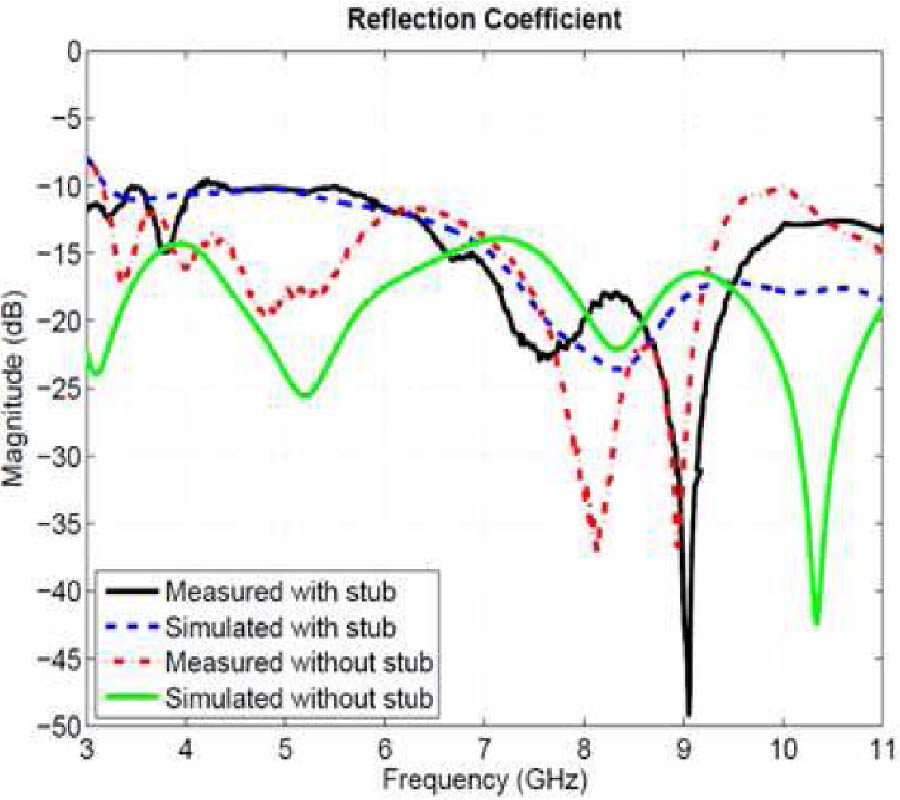
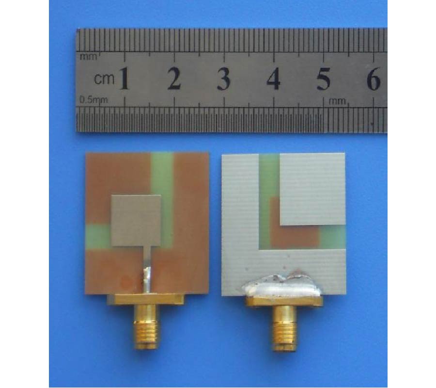
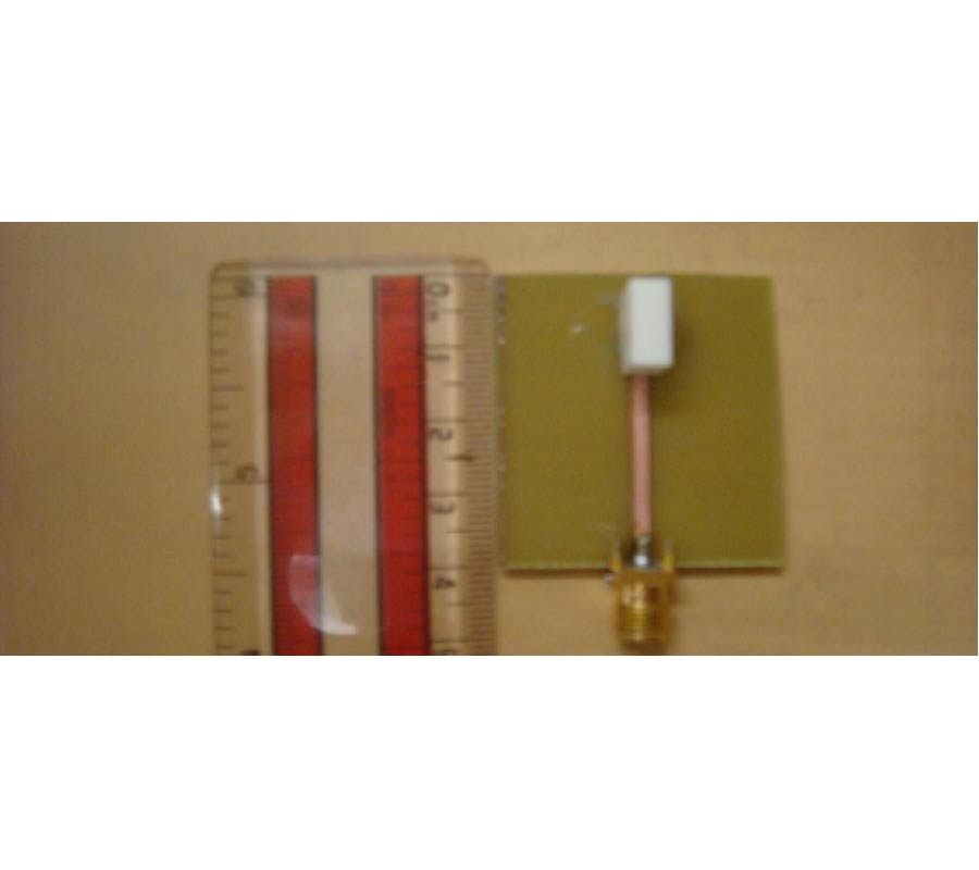
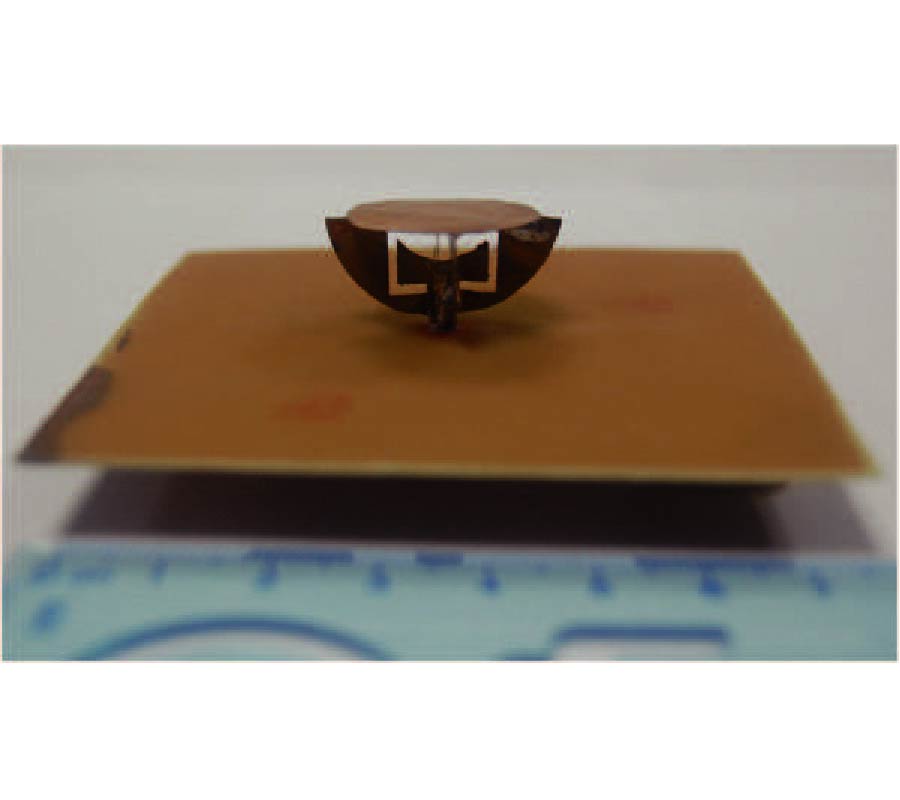
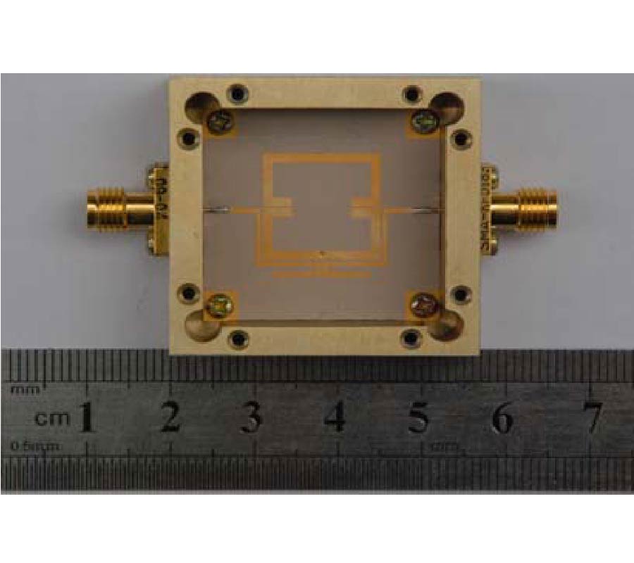
A novel wafer-dipole printed antenna fed by balanced micro-strip line is proposed, and the adoption of the balanced micro-strip line can effectively solve the feeding problem of the UWB dipole antenna. The wafer-dipole and a branch of the balanced microstripline are printed on one side of FR-4 substrate (1mm thickness), and the later is connected to a wafer directly, while the other branch is printed on the back side of the substrate and connected the other wafer with a via-hole. The measured results show that the antenna impedance bandwidth is from 3.0 GHz to 15.0 GHz with VSWR < 2, and the ratio bandwidth is about 5:1. Moreover, the antenna size is just 40 mm×20 mm with simple structure, which is well suited for short-distance UWB communications.
STUDY ON A MINIATURE UWB WAFER-DIPOLE PRINTED ANTENNA FED BY BALANCED MICRO-STRIP LINE
2011-01-13
PIER C
Vol. 19, 61-72, 2011
download: 193
A k -Band Transmitter Front-End Based on Differential Switches in 0.13-µm CMOS Technology
Hung-Chi Wang , Jyh-Ching Juang and Chun-Lin Lu
This paper presents the design and test results of a 20-GHz transmitter front-end implemented in the TSMC 0.13-μm CMOS process. The chip consists of a voltage-controlled oscillator (VCO), an RC phase splitter, and two differential switches. To realize the K-band transmitter function, the two different switches are designed to serve the purpose of frequency doubler and phase modulator, respectively. These two features are verified in the implemented chip and, as a result, the chip can serve as a transmitter front-end. The measured total current consumption of the chip core circuit is 26 mA under a DC supply voltage of 1.2 V. The chip size is 1.03×0.93 mm2.
A K-BAND TRANSMITTER FRONT-END BASED ON DIFFERENTIAL SWITCHES IN 0.13-µm CMOS TECHNOLOGY
2011-01-10
PIER C
Vol. 19, 47-59, 2011
download: 241
The Effect of Electrode Materials on the Optical Characteristics of Infrared Quantum Dot-Light Emitting Devices
Ahmed E. Farghal , Swelem Wageh and Atef El-Sayed Abou El-Azm
We present an optical model based on Green function to investigate the effect of using Single Wall Carbon Nanotube (SWCNT) as anode for infrared light emitting devices (IR QD-LEDs). To the best of our knowledge there is no report in using SWCNT as anode in IR QD-LEDs. We have studied the emitted power distribution among the different optical modes (air, substrate, anode/organics, and surface plasmon modes (SP)), angular intensity distribution, and the emission spectral characteristics. We have found that the light outcoupling efficiency of IR QD-LEDs based on SWCNT as anode was increased nearly by a factor of 4 relative to that one based on indium-tin oxide (ITO). We also investigated the effect of using different cathode materials on the optical characteristics of IR QD-LEDs.
THE EFFECT OF ELECTRODE MATERIALS ON THE OPTICAL CHARACTERISTICS OF INFRARED QUANTUM DOT-LIGHT EMITTING DEVICES
2011-01-09
PIER C
Vol. 19, 37-46, 2011
download: 226
Design of Compact Dual-Frequency Wilkinson Power Divider Using Non-Uniform Transmission Lines
Khair Ayman Al Shamaileh and Nihad I. Dib
In this paper, a reduced size dual-frequency Wilkinson power divider (WPD) is presented. The miniaturization is accomplished by using two sections of non-uniform transmission line transformers in place of the two uniform sections in the conventional dual-frequency WPD. Two isolation resistors are also used to achieve good isolation between the output ports. Optimization is carried out based on simple uniform transmission line theory. For verification purposes, a dual-frequency WPD operating at 0.5 GHz and 1 GHz is designed, analyzed and fabricated.
DESIGN OF COMPACT DUAL-FREQUENCY WILKINSON POWER DIVIDER USING NON-UNIFORM TRANSMISSION LINES
2010-12-24
PIER C
Vol. 19, 25-35, 2011
download: 282
Printed Loop Antenna Integrated into a Compact, Outdoor WLAN Access Point with Dual-Polarized Radiation
Saou-Wen Su
A printed loop antenna for integration into a compact, outdoor WLAN access point (AP) is presented. The loop design has a one-wavelength, resonant structure with respect to the center operating frequency of the 2.4 GHz band and is formed on a 1.6-mm thick FR4 substrate. The antenna substrate is further stacked above a system (PCB) of an outdoor AP by a small distance. In this study, the proposed design integrates the system printed circuit board PCB serving as an efficient reflector for the loop into an internal AP antenna solution. The results showed that by feeding the proposed square loop at one corner and adding the tuning portion at the diagonal corner, the dual-polarized radiation in the two major planes and good impedance matching over the band can be attained. High gain, directional radiation patterns were also obtained.
PRINTED LOOP ANTENNA INTEGRATED INTO A COMPACT, OUTDOOR WLAN ACCESS POINT WITH DUAL-POLARIZED RADIATION
2010-12-23
PIER C
Vol. 19, 15-24, 2011
download: 222
Analysis and Design of Wideband Planar Yagi- and BI-Yagi Arrays with Photonic Band Gap
Maher M. Abdel-Razzak
In this work, the analysis and design of wideband microstrip yagi and bi-yagi antenna arrays with photonic band gap (PBG) is presented. By using the bi-yagi planar array, a high directive gain and a high frontto-back ratio are achieved in comparison with that of the single microstrip yagi structure. The current distribution, the return loss, the radiation pattern, and the input impedance are calculated. For a single yagi, wide bandwidth up to 12.81% at 10.15 GHz is obtained. However, a high directive gain is achieved with the bi-yagi. The PBG structures force the antennas to have stop band at the higher end of the operating band. In addition, it increases the front-to back (F/B) ratio. The finite difference time domain (FDTD) with the perfect matched (PML) and a numerical package based on the method of moment (MOM) are used in the present analysis and design. A closed form based on an approximate equivalent circuit is used to get approximate dimensions of the PBG structures.
ANALYSIS AND DESIGN OF WIDEBAND PLANAR YAGI- AND BI-YAGI ARRAYS WITH PHOTONIC BAND GAP
2010-12-23
PIER C
Vol. 19, 1-14, 2011
download: 245
Circuit-Based Analysis of Tapped-in Coupling Between Combline Resonators Applicable in Wideband Filter Designs
Baharak Mohajer-Iravani and Mahmoud A. El Sabbagh
We showed that creating coupling between resonators through transverse electromagnetic transmission line directly tapped into both resonators provides a viable solution for the design of wideband microwave components where strong coupling values are required. However, more analysis is needed to explain the coupling mechanism and its limitation. In this work, we present the developed equivalent circuit model which is comprised only of lumped elements for comprehensive analysis of the tapped-in coupling between planar or cavity combline resonators. The effects of lumped elements which are in correspondence to physical parameters on coupling value and resonant center frequency are derived. The circuit model predicts that this coupling mechanism by adjusting the design parameters of coupling section simply realizes any required strength of coupling between resonators, i.e., from weak values close to zero up to strong values close to unity. Therefore, wideband filters are easily designed and their bandwidth can be controlled based on inter-resonator tapped-in coupling. This fact is validated through measurements for two-coupled resonators with unloaded resonant frequency of 1.45 GHz. The bandwidth is extended to 90% via tapped-in method. The total dimensions of structure are λ/4 × λ/18 × λ/72.
CIRCUIT-BASED ANALYSIS OF TAPPED-IN COUPLING BETWEEN COMBLINE RESONATORS APPLICABLE IN WIDEBAND FILTER DESIGNS