Anatomically and Dielectrically Realistic Microwave Head Phantom with Circulation and Reconfigurable Lesions
Barry McDermott ,
Emily Porter ,
Adam Santorelli ,
Brendan Divilly ,
Liam Morris ,
Marggie Jones ,
Brian McGinley and
Martin O'Halloran
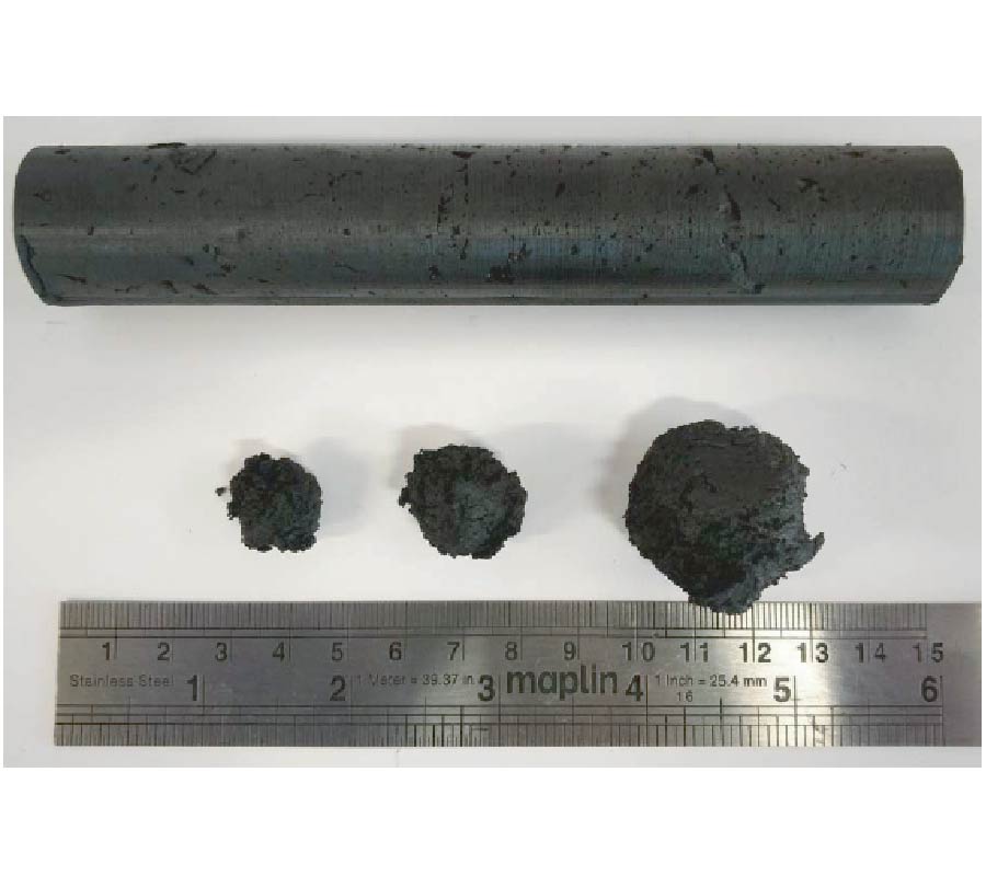
Phantoms provide valuable test platforms for developing medical devices. Solid materials in particular allow fabrication of stable and robust models. This paper presents a novel, anatomically realistic, multi-layered head phantom made from dielectrically accurate, stable, easily mouldable, low-cost tissue-mimicking materials for testing of microwave diagnostic systems. Also incorporated is a mechanism for inserting reconfigurable lesions and a novel circulatory system modelling physiology. Tissue-mimicking materials composed of graphite, carbon black, and polyurethane with small volumes of acetone or isopropanol were fabricated and dielectric properties were measured across the 1 - 8.5 GHz band. The tissuemimicking material properties were adjusted until their dielectric properties matched those of reference values for target tissues of interest, thereby emulating: weighted aggregates of head tissues external to the brain, tissues comprising the brain, and blood. 3D printed anatomically realistic head and brain moulds cast the phantom mixtures for each layer. Cylindrical holes in the brain layer allow insertion of pathological lesion phantoms, such as haemorrhages. Tubing embedded in the brain layer forms a symmetrical loop providing a novel simplistic model of circulation. The resulting head phantom is anatomically realistic, dielectrically stable, enables pathology modelling, and has, uniquely, a circulatory loop. This novel head phantom provides a valuable test platform for microwave diagnostic studies.