A Contactless System for the Dielectric Characterization of Liquid Drops
Gabriel Galindo-Romera ,
Javier Carnerero-Cano ,
José Juan Martínez-Martínez ,
Alejandro Rivera-Lavado and
Francisco Javier Herraiz-Martínez
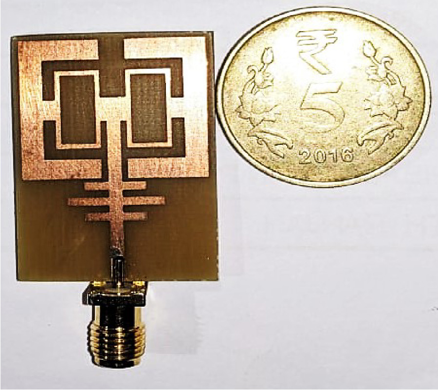
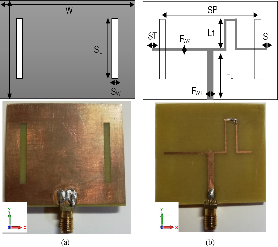
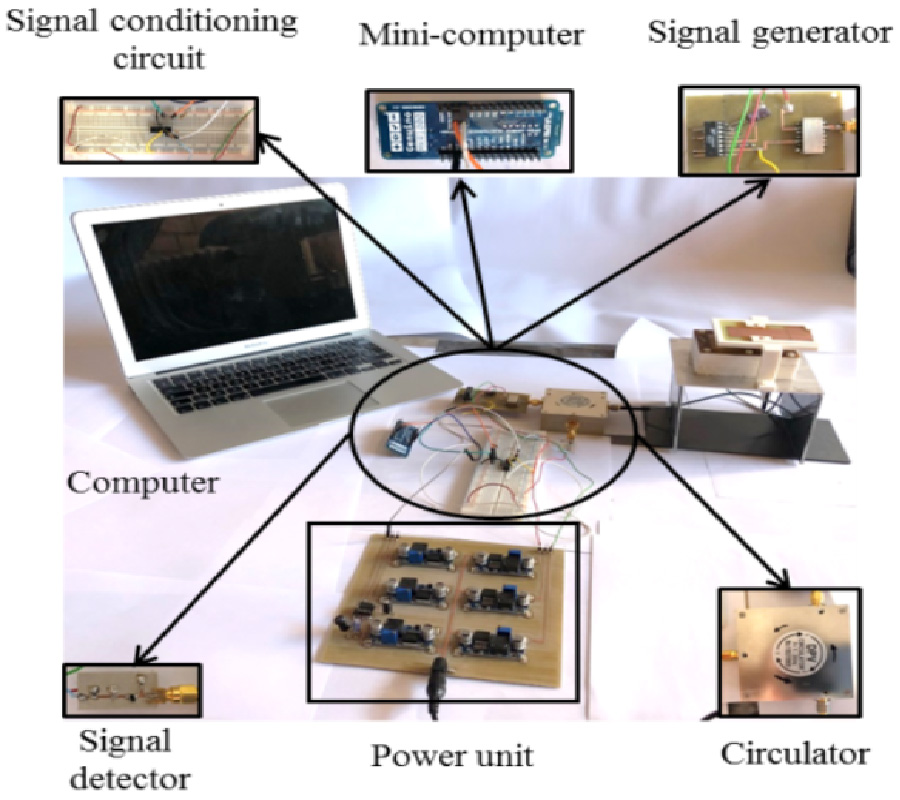
The present article shows the design, implementation, and measurement of a compact contactless electronic system for sensing small volumes of liquids. The system is based on two elements: an electronic reader and a passive sensor. The proposed sensor consists of a printed monopole antenna loaded with two Split-Ring Resonators. This results in a fully-passive and single-layer low-cost design. To allow the sensing of small volumes of liquids, a 1-mm-thick adhesive Kapton layer was attached on the top layer of the sensor, and two drop tanks were added to the structure. On the other hand, the reader was designed following a layered approach, which allows us to develop compact and low-cost electronic sensor readers for the Internet of Things. The resulting reader contains a Radio-Frequency interface for the generation of detection of signals, a minicomputer, and the radiating interface. This interface includes a patch antenna that allows us to interrogate the contactless sensor within a 1-cm range. The whole system was manufactured and tested. The total dimensions of the reader are 15 cm × 15 cm, and its weight is below 1 kg. These imply a dramatic form factor and weight reductions with respect to previous readers. Moreover, the manufactured system was used to measure the dielectric permittivity of different liquid drops. Results show that only 4 ml of liquid were needed to determine the dielectric permittivity with a 0.27% error. This volume means a 98.4% reduction compared to submersible sensors which can be found in the literature.