Vol. 109
Latest Volume
All Volumes
PIERB 109 [2024] PIERB 108 [2024] PIERB 107 [2024] PIERB 106 [2024] PIERB 105 [2024] PIERB 104 [2024] PIERB 103 [2023] PIERB 102 [2023] PIERB 101 [2023] PIERB 100 [2023] PIERB 99 [2023] PIERB 98 [2023] PIERB 97 [2022] PIERB 96 [2022] PIERB 95 [2022] PIERB 94 [2021] PIERB 93 [2021] PIERB 92 [2021] PIERB 91 [2021] PIERB 90 [2021] PIERB 89 [2020] PIERB 88 [2020] PIERB 87 [2020] PIERB 86 [2020] PIERB 85 [2019] PIERB 84 [2019] PIERB 83 [2019] PIERB 82 [2018] PIERB 81 [2018] PIERB 80 [2018] PIERB 79 [2017] PIERB 78 [2017] PIERB 77 [2017] PIERB 76 [2017] PIERB 75 [2017] PIERB 74 [2017] PIERB 73 [2017] PIERB 72 [2017] PIERB 71 [2016] PIERB 70 [2016] PIERB 69 [2016] PIERB 68 [2016] PIERB 67 [2016] PIERB 66 [2016] PIERB 65 [2016] PIERB 64 [2015] PIERB 63 [2015] PIERB 62 [2015] PIERB 61 [2014] PIERB 60 [2014] PIERB 59 [2014] PIERB 58 [2014] PIERB 57 [2014] PIERB 56 [2013] PIERB 55 [2013] PIERB 54 [2013] PIERB 53 [2013] PIERB 52 [2013] PIERB 51 [2013] PIERB 50 [2013] PIERB 49 [2013] PIERB 48 [2013] PIERB 47 [2013] PIERB 46 [2013] PIERB 45 [2012] PIERB 44 [2012] PIERB 43 [2012] PIERB 42 [2012] PIERB 41 [2012] PIERB 40 [2012] PIERB 39 [2012] PIERB 38 [2012] PIERB 37 [2012] PIERB 36 [2012] PIERB 35 [2011] PIERB 34 [2011] PIERB 33 [2011] PIERB 32 [2011] PIERB 31 [2011] PIERB 30 [2011] PIERB 29 [2011] PIERB 28 [2011] PIERB 27 [2011] PIERB 26 [2010] PIERB 25 [2010] PIERB 24 [2010] PIERB 23 [2010] PIERB 22 [2010] PIERB 21 [2010] PIERB 20 [2010] PIERB 19 [2010] PIERB 18 [2009] PIERB 17 [2009] PIERB 16 [2009] PIERB 15 [2009] PIERB 14 [2009] PIERB 13 [2009] PIERB 12 [2009] PIERB 11 [2009] PIERB 10 [2008] PIERB 9 [2008] PIERB 8 [2008] PIERB 7 [2008] PIERB 6 [2008] PIERB 5 [2008] PIERB 4 [2008] PIERB 3 [2008] PIERB 2 [2008] PIERB 1 [2008]
2024-12-11
PIER B
Vol. 109, 95-112, 2024
download: 20
Free Space Transmission Lines in Receiving Antenna Operation
Reuven Ianconescu and Vladimir Vulfin
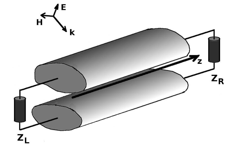
This work derives exact expressions for the voltage and current induced into a two conductors non-isolated transmission line by an incident plane wave. The methodology is to use the transmission line radiating properties to derive scattering matrices and make use of reciprocity to derive the response to the incident wave. This methodology to derive receiving characteristics from the radiation properties via a scattering matrix is novel, and we already started to implement it to additional cases. An immediate advantage we obtained from this method is the derivation of a very simple analytic expression for the voltage and current for a matched transmission line. The analysis is in the frequency domain, and it considers transmission lines of any small electric cross section, incident by a plane wave from any direction and polarization. The analytic results are validated by successful comparison with ANSYS commercial software simulation results, and compatible with other published results.
Free Space Transmission Lines in Receiving Antenna Operation
2024-12-05
PIER B
Vol. 109, 81-93, 2024
download: 136
Design of a Crescent Moon-Shaped Reconfigurable Patch Antenna Using a PIN Diode for 5G Sub-6 GHz and Multistandard Wireless Applications
Salah Eddine El Aoud , Hind Abbaoui , Omaima Benkhadda , Sanae Attioui , Nasima El Assri , Saïda Ibnyaich , Abdelouhab Zeroual , Mohd Muzafar Ismail and Ahmed Jamal Abdullah Al-Gburi
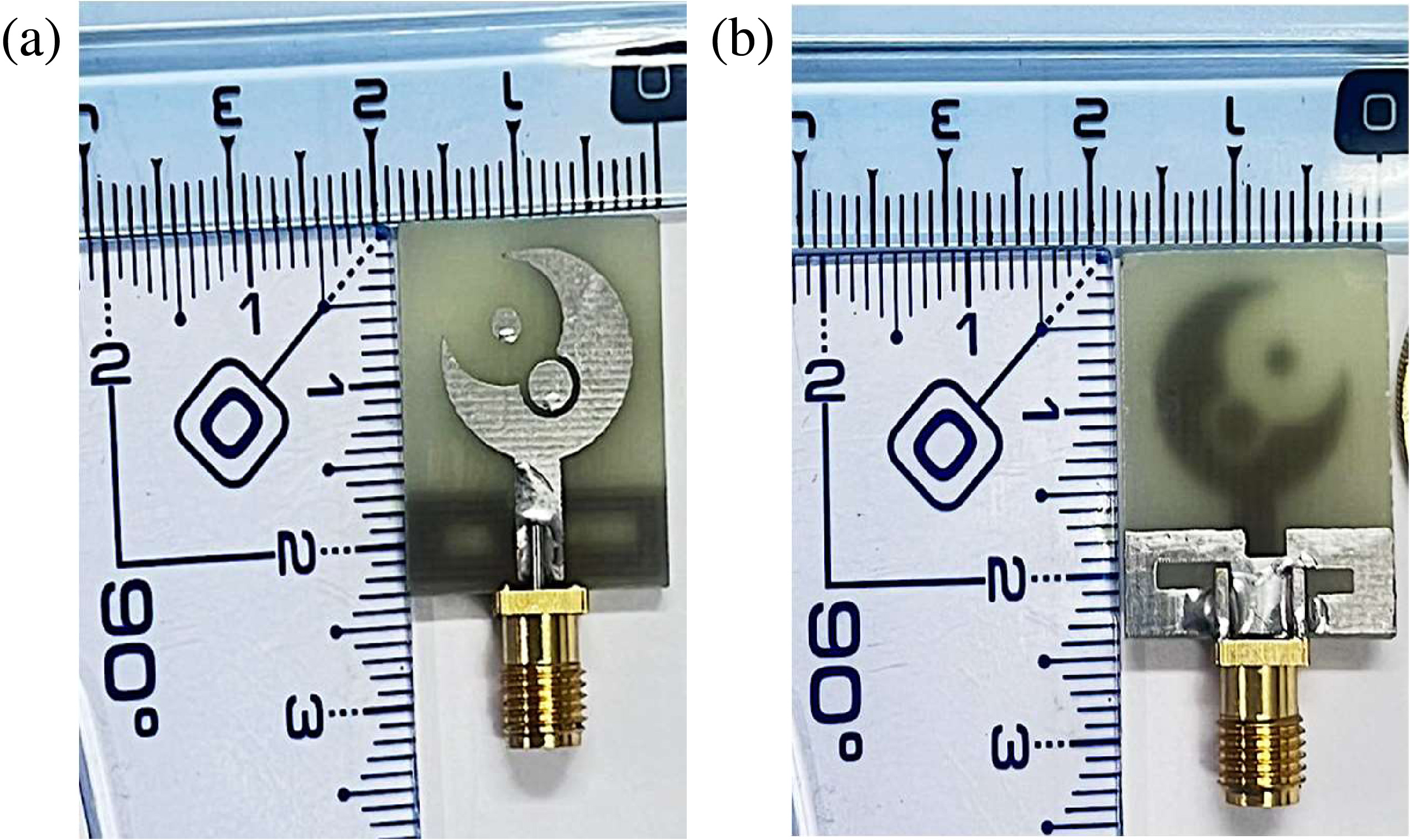
This research explores the versatility of a miniature reconfigurable antenna designed for a variety of wireless applications: 5G (IEEE 802.15.3), WLAN (IEEE 802.11), V2X (IEEE 802.11 p), WiMAX (IEEE 802.166), Wi-Fi 6E (IEEE 802.11 ax), Wi-Fi 7 (IEEE 802.11 be), C-band (from 4 GHz to 8 GHz), and X-band (from 8 GHz to 12 GHz). The antenna utilizes an FR4-Epoxy substrate with a thickness of 1.6 mm and a relative permittivity of 4.3. To enable frequency reconfigurability, the patch is equipped with two PIN diodes, which can be positioned at different locations to adjust the antenna's operational frequency range. This reconfigurability allows the antenna to maintain its size while changing its frequency range according to the state of the PIN diodes. The strength of our work lies in achieving exceptional electrical performance while maintaining a small size, cost-effective, and compact design. The antenna demonstrates an almost omnidirectional radiation pattern across all frequency ranges. Additionally, the simulated reflection coefficient remains within the ideal range for every frequency band. The antenna's overall dimension is 22 × 18 × 1.6 mm3o/4 × λo/5 × λo/56) (with λo being the free space wavelength at the lowest resonating frequency and for the proposed antenna its value equal to 91.18 mm) with a miniaturization rate equal to 75.25%. This compact antenna is designed to operate across multiple frequencies, making it suitable for various applications, particularly in wireless communication systems. Its versatility also makes it a promising candidate for future portable devices, sensor networks, and telecommunication applications. The performance metrics, including return loss and radiation pattern, are presented, demonstrating strong performance across these parameters. The analyses were conducted using the CST Studio Suite, which provided detailed insights into the antenna's functionality and effectiveness.
Design of a Crescent Moon-shaped Reconfigurable Patch Antenna Using a PIN Diode for 5G Sub-6 GHz and Multistandard Wireless Applications
2024-11-28
PIER B
Vol. 109, 69-80, 2024
download: 26
A Technique for Alternating Generation of Single and Multi-Beams from Circularly Polarized Antenna Arrays
David Pouhè
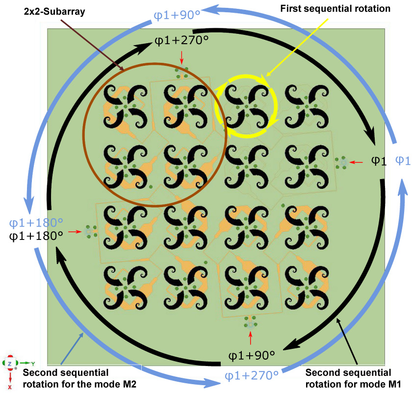
A simple technique for generating single and multiple beams from antenna arrays is presented. The approach is based on the multistage sequential rotation technique. A new feature in using multistage sequential rotation is provided. It is demonstrated that by applying a controlled second sequential rotation, circularly polarized antenna arrays operating alternately in a single-beam mode M1 and multi-beam mode M2 in the same frequency band can be designed. Proof-of-concept is provided mathematically and through numerical simulations in light of case studies. The approach can not only be applied to large antenna arrays following a modular principle adapted to the array size and needed applications without loss of generality, but it also paves the way for the manufacture of circularly polarized antennas operating alternately or simultaneously in both modes in the same frequency band. In addition, antennas designed using the proposed approach may have a wide range of applications ranging from monopulse radar to antennas for compensation of interference and blockage in dynamic communication environments.
A Technique for Alternating Generation of Single and Multi-Beams from Circularly Polarized Antenna Arrays
2024-11-21
PIER B
Vol. 109, 57-67, 2024
download: 38
Analysis of Eddy Current Losses and Stresses in High-Speed Permanent Magnet Synchronous Motors with Frameless Torque
Xiping Liu , Haiao Sun , Zhangqi Liu and Canwei Zhang
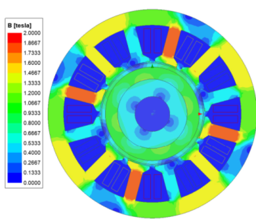
In this paper, a high-speed frameless torque permanent magnet synchronous motor is designed to determine the optimal structure of the rotor by comparing the air gap magnetism, cogging torque and output torque of the motor through finite element analysis. The effects of different material rotor sheaths on eddy current loss are compared and analyzed, and the copper shield is used to optimize the rotor eddy current loss of the high-speed frameless torque motor. Through the analytical method, based on the theory of thick-walled cylinder, the stress calculation is carried out on the multilayer rotor structure of the high-speed permanent magnet synchronous motor with copper shielding layer, and a comparative analysis is carried out with the simulation results to verify the validity of the analytical calculations and the reasonableness of the optimization of the rotor eddy current loss.
Analysis of Eddy Current Losses and Stresses in High-speed Permanent Magnet Synchronous Motors with Frameless Torque
2024-11-19
PIER B
Vol. 109, 41-56, 2024
download: 89
Design of F-Shaped Parasitic MIMO Antenna with DGS for Vehicle-to-Everything Communication
Maruti R. Jadhav and Uttam L. Bombale
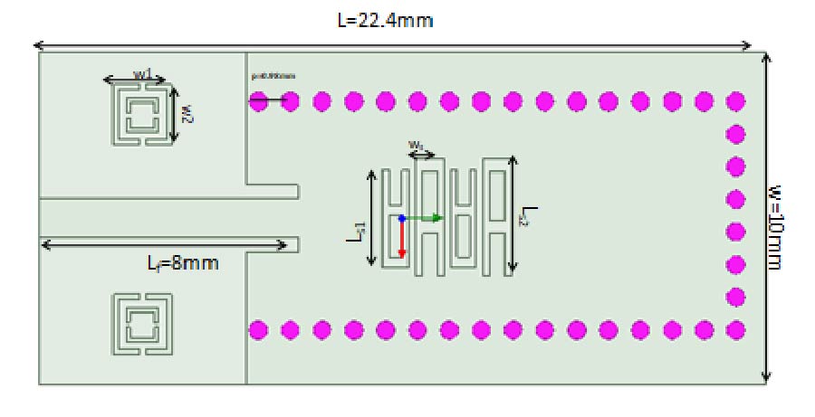
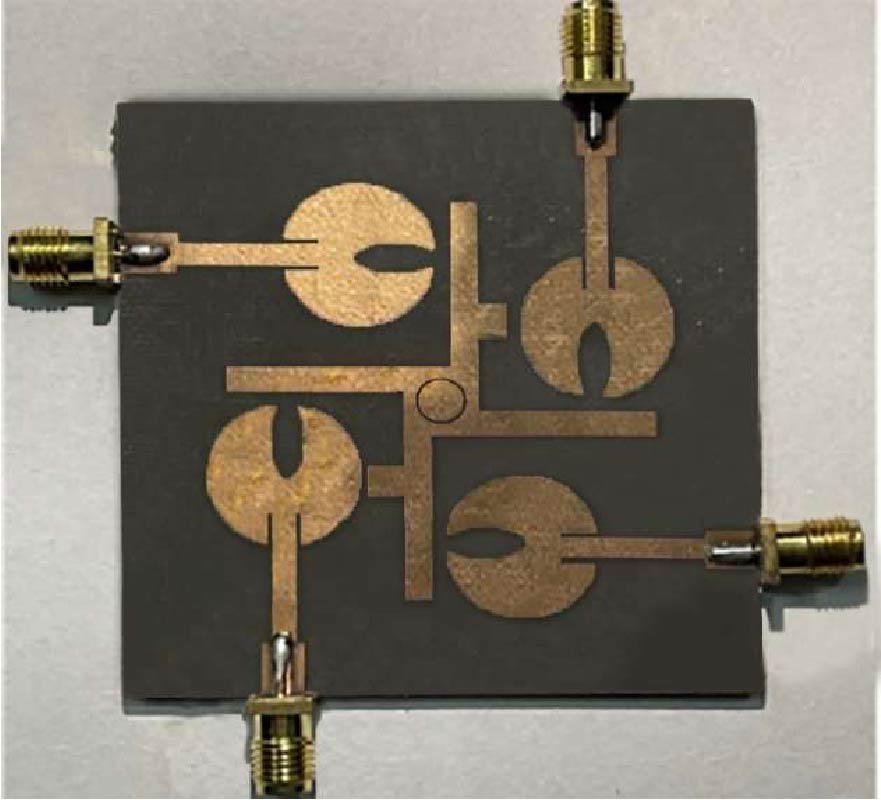
Multiple-Input Multiple-Output (MIMO) antennas are essential for transmitting and receiving information in Vehicle to Everything (V2X) communication. However, the MIMO antenna designs at V2X are complex because of the mutual coupling problem. Several approaches have been designed to improve antenna isolation. However, these approaches have drawbacks like gain, bandwidth, and radiation efficiency reductions. This work introduces a compact four-port MIMO antenna that operates at a 5.85 GHz to 5.9 GHz frequency range for V2X communication. Here, the slotted circular microstrip patch MIMO antenna is considered. The antenna's length, width, and patch are optimized by metaheuristic optimization called Aquila Optimization (AO). A substrate Rogers RT5880, which has a defected ground structure (DGS) and a parasitic patch, is used to design the antenna. F-shaped parasitic elements are placed near each antenna element to improve isolation. The DGS with a U-shaped parasitic element minimizes the mutual coupling among the adjacent antenna elements. The considered overall dimension has a compact size, and it achieves better envelope correlation coefficient (ECC < 0.5), total active reflection coefficient (TARC < -10 dB), diversity gain (DG > 9.9 dB), channel capacity loss (CCL < 0.4), and mean effective gain (MEG < 3 dB) at 5.88 GHz. Hence, it is proposed that the developed design is useful for applying V2X communications.
Design of F-shaped Parasitic MIMO Antenna with DGS for Vehicle-to-everything Communication
2024-11-16
PIER B
Vol. 109, 29-40, 2024
download: 68
Design and Optimization of Series-Connected Hybrid Excitation Permanent Magnet Synchronous Motor
Jianwei Liang , Tian Song , Peiyao Guo , Xiubin Zhu , Zhangsheng Liu and Yuqian Zhao
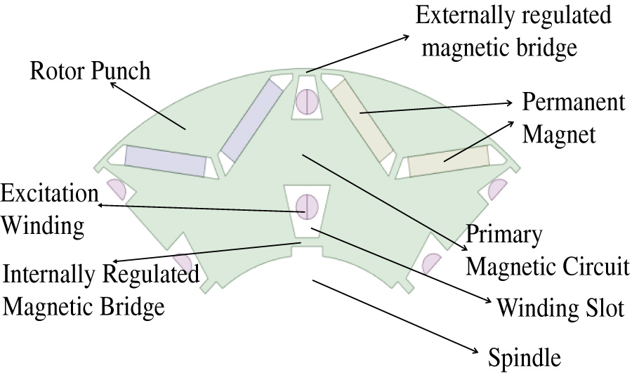
To address the problems that the traditional permanent magnet synchronous motor air-gap flux is difficult to adjust and that the weak magnetic speed expansion ability is poor, a new series-connected hybrid excitation permanent magnet synchronous motor is proposed. A DC excitation winding is added to the rotor, allowing the excitation field generated by this winding to form a series connection with the magnetic field of the permanent magnets. The structure of this paper includes an overview of the novel rotor structure and principle of operation. For the complex rotor structure, a multi-objective genetic algorithm is used for optimisation, followed by finite element analysis to compare the performance of the initial motor, the optimised motor and the conventional motor in terms of no-load air-gap magnetism, reverse electromotive force as well as output torque and efficiency. The magnetic load of the motor in the demagnetized state is increased from 0.2 to 0.266 compared to the unexcited state, and the magnetization capacity is improved by 33%. The output torque of the optimized motor is 252 N.m at low speed; the output torque of the conventional motor is 220 N.m; and the starting torque of the motor is improved by 14.5%. The maximum speed is increased from 10,000 rpm to 11,500 rpm, and the speed expansion capacity is improved by 15%. The effectiveness and feasibility of the series-connected hybrid excitation permanent magnet synchronous motor are verified.
Design and Optimization of Series-connected Hybrid Excitation Permanent Magnet Synchronous Motor
2024-11-11
PIER B
Vol. 109, 17-28, 2024
download: 171
A Low-Profile Single-Layered Wideband Combinational Reconfigurable Antenna for 4G and 5G Applications
Sweta Agarwal , Akanksha Singh and Manoj Kumar Meshram
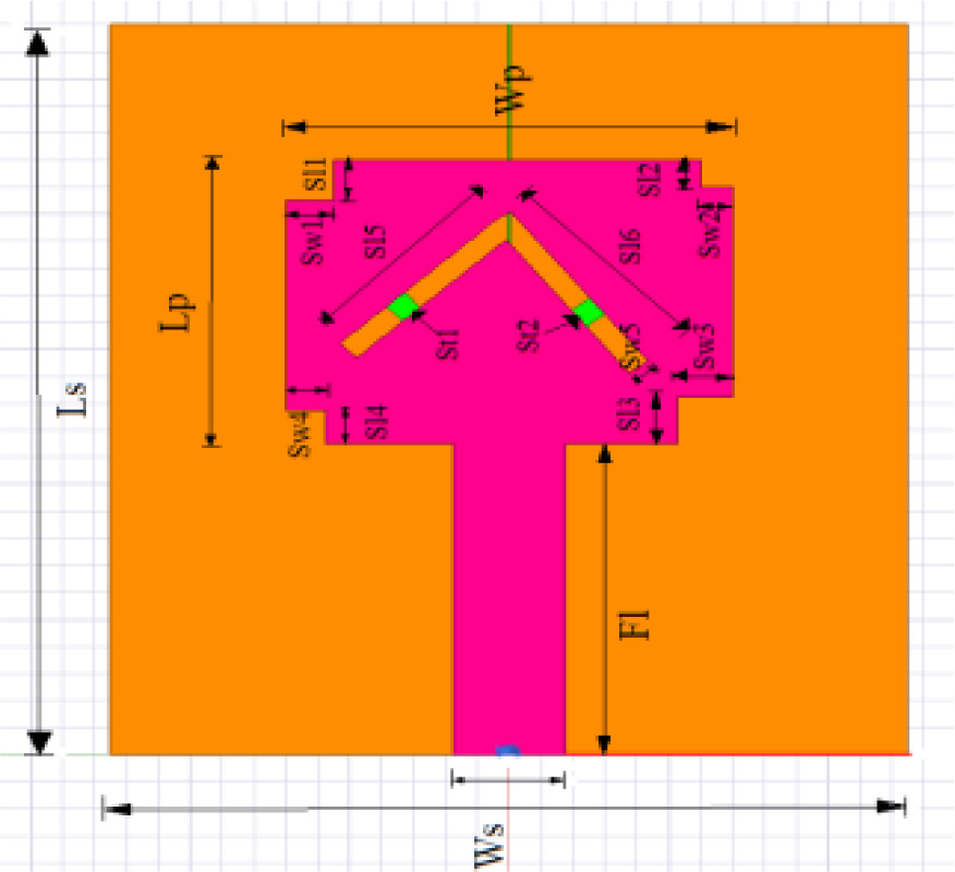
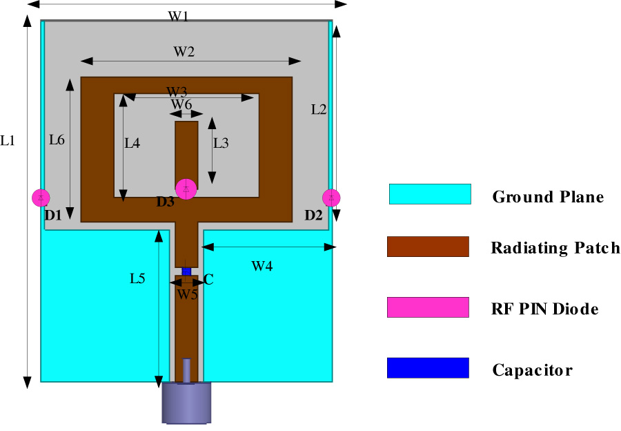
A single-layered monopole wideband combinational reconfigurable antenna for 4G and 5G applications is presented in this paper. Coplanar waveguide (CPW) feeding method is utilized to get single-layered structure. The three characteristics of this antenna are reconfigurable: frequency, polalization, and radiation pattern. This antenna consists of a parasitic element attached to a rectangular ring antenna. An RF-PIN diode is used to connect this parasitic element to the loop antenna. Additionally, two parasitic elements are connected to the ground plane of the proposed antenna via a pair of RF-PIN diodes. The suggested antenna functions in seven distinct states with the use of these three RF-PIN diodes. The suggested antenna operates at frequencies of 3.24-3.52 GHz, 2.78-2.94 GHz, and 2.54-2.9 GHz with an omnidirectional radiation pattern in states 1, 2, and 5. In states 3 and 4, it has an end-fire radiation pattern in the left and right directions of the proposed antenna, covering a wide frequency band of 2.47-3.57 GHz. Lastly, the suggested antenna operates in dual bands at frequencies of 2.49–2.9 GHz and 3.6-3.76 GHz in states 6 and 7. It offers reconfigurability of polarization at the higher band. The suggested antenna is made of glass epoxy FR-4. For verification of the suggested antenna, the prototype is designed and tested. The simulated and experimental results agree quite well.
A Low-profile Single-layered Wideband Combinational Reconfigurable Antenna for 4G and 5G Applications
2024-10-26
PIER B
Vol. 109, 1-16, 2024
download: 100
Ultrawideband High-Gain Stacked Microstrip Antenna with Modified E-Shaped Active Exciter and Four Single-Sided Bowtie Passive Elements
Mikhail S. Shishkin
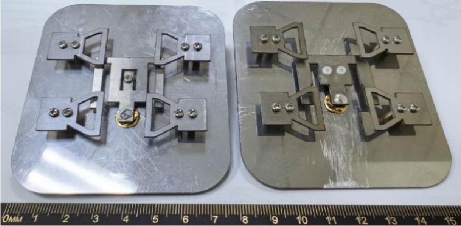
The article presents a method that allows for the high gain of a stacked microstrip antenna on an air substrate in an ultrawide frequency range. The method uses an active exciter in the form of a modified E-shaped patch, as well as four single-sided bowtie passive elements placed in the corners above the active one. The active element can match an antenna in an ultra-wide frequency range (up to 100%) with an impedance bandwidth matching of 10 dB or better, whereas passive elements are able to produce unidirectional radiation in the range of approximately 70-80% with a gain of more than 10 dBi. Based on the method under study, an ultrawideband antenna design was made which operates in a frequency band of 3,915 to 11,046 MHz (95.3%) with an impedance bandwidth matching of 10 dB and a bandwidth about 83% with |S11| ≤ -15 dB; the usable bandwidth with a gain of more than 10 dBi in the normal direction to the antenna plane with a cross-polar discrimination more than 55 dB is 77% (3,925-8,837 MHz). At frequencies below 4 GHz and above 9 GHz, the phase center shifts, and accordingly, the main lobe of the radiation pattern (radiation maximum) deflects. All antenna elements (one active and four passives) are made of sheet metal (e.g., stainless steel) and are connected to the conductive screen by steel or dielectric racks. The antenna dimensions are 1.05λmax × 1.2λmax × 0.1λmax (1.7λ0 × 1.9λ0 × 0.2λ0). Owing to its high performance, the antenna may be used as a measuring device in radio monitoring systems or in laboratories.
Ultrawideband High-gain Stacked Microstrip Antenna with Modified E-shaped Active Exciter and Four Single-sided Bowtie Passive Elements