Search Results(13979)

2022-09-09
PIER C
Vol. 124, 23-32
Gain Enhanced Characteristics of Miniaturized Antenna for 5 GHz WLAN Application
Kakani Suvarna , Nallagarla Ramamurthy and Dupakuntla Vishnu Vardhan
In this article, a miniaturized pentagonal slot antenna (PSA) with a Meander Koch Defected Ground Structures (MK-DGS) and metamaterials (MTM) is proposed for 5 GHz WLAN application. Initially, a Meander Koch DGS was used to lower the resonant frequency of the basic PSA, from 13.1 GHz to 5 GHz. The proposed antenna has been 61.83% miniaturized, close to an electrically small antenna. The performance characteristics of a basic PSA using MK-DGS and MTM superstrate, which improves efficiency, directivity, and peak gain, are also discussed. An antenna with dimensions of 15 × 15 mm2 (or) 0.25λ0 × 0.25λ0 mm2 at a thickness of h1 = 1.6 mm is designed, fabricated, and tested on an FR4 epoxy substrate, and its impact on size reduction performance is evaluated. The gain at 5 GHz is increased from 3.15 to 7.84 dBi by introducing an MTM superstrate made of RT Duriod at a thickness of 1.575 mm above the miniaturized PSA at 17 mm. Test results of the prototype model are corroborated by the simulated results of the proposed model.
GAIN ENHANCED CHARACTERISTICS OF MINIATURIZED ANTENNA FOR 5 GHZ WLAN APPLICATION
2022-09-09
PIER C
Vol. 124, 11-22
Design and Analysis of Quad-Band Notch Characteristics UWB Antenna Using SLR Circuits
Navamani Parthiban and Mohamed Ismail Mohamed
In this paper, a quad-band notch characteristics ultra-wideband (UWB) antenna for Wi-MAX, L-WLAN, U-WLAN, and C-band applications is presented. The initial UWB antenna bandwidth is achieved in the 2 to 12.5 GHz frequency band by using the partial ground method. Spiral lossy resonator (SLR) slots are loaded into the UWB ground structure to achieve quad-band notch characteristics. Each SLRS circuit is accountable for a single notch characteristic by losing EM power at the notch frequency. A quad-band notch is accomplished in this antenna for WiMAX (3.24 to 3.56 GHz), L-WLAN (4.76 to 5.34 GHz), U-WLAN (5.58 to 5.91 GHz), and C-band (7.37 to 7.71 GHz) by loading four SLR slots circuits into the UWB antenna. The proposed antenna is engraved on a Rogers RO4003C (3.55) substrate having an overall volume of 50*40*1.524 mm3. The proposed antenna's performance has been verified through simulation and experiments.
DESIGN AND ANALYSIS OF QUAD-BAND NOTCH CHARACTERISTICS UWB ANTENNA USING SLR CIRCUITS
2022-09-09
PIER M
Vol. 113, 73-86
Bistatic RCS Control on Slot-Sinuous Antenna by Adding 3 and 5 Parasitic Ellipses Openings
Elson Agastra , Alaksander Biberaj , Olimpjon Shurdi and Bexhet Kamo
In this paper, an ultra-wide band modified slot-sinuous antenna has been designed to enhance bistatic radar cross section (RCS) response. The design procedure consists of adding three or five parasitic ellipses openings to each of the slot-sinuous arm cells. The parasitic ellipsis allows to control bistatic RCS without impacting antenna radiation characteristics. Parasitic ellipses opening dimensions are small compared to the relative wavelength of the signal on each active region of the antenna. Ellipses deploy over the entire sinuous arms are scaled by the same expansion coefficient used to design the antenna itself. In the proposed design, ellipses parameters such as ellipses axis, radial position, and relative angle position on the sinuous cell are key parameters to be optimized for bistatic RCS reduction. The total number of designing parameters is finite, but their combination is infinite, which leads to the possibility of designing different antennas based on the required designing goals. The proposed solution and the results presented in this work show the applicability of the designing parameters to control bistatic RCS on active region antennas.
Bistatic RCS Control on Slot-sinuous Antenna by Adding 3 and 5 Parasitic Ellipses Openings
2022-09-09
PIER M
Vol. 113, 59-71
Parameter Identification Based on Chaotic Map Simulated Annealing Genetic Algorithm for PMSWG
Yang Zhang , Chao Zhang and Zhun Cheng
Traditional genetic algorithm identification of permanent magnet synchronous wind generator (PMSWG) parameters is easy to fall into local optimum, resulting in low accuracy of parameter identification results and slow convergence, which reduces the accuracy of parameter tuning of proportional-integral (PI) controller. Aiming at this problem, a chaotic mapping simulated annealing genetic algorithm (CMSAGA) for identifying PMSWG parameters is proposed. The traditional genetic algorithm (GA) has the ability of global random search, combined with the probability breakthrough characteristic of the simulated annealing (SA) algorithm, which avoids the parameter identification result falling into the local optimum and finally tends to the global optimum. With the increase of iteration times, the initial population is mapped with tent chaos mapping theory, and the optimal value of the population is disturbed in each iteration to increase the diversity of the population, making the proposed algorithm converge faster and improve the accuracy. Experiments show that the proposed algorithm has good accuracy and convergence speed, PMSWG stator resistance, stator winding d-q axis inductance and permanent magnet flux can be identified.
PARAMETER IDENTIFICATION BASED ON CHAOTIC MAP SIMULATED ANNEALING GENETIC ALGORITHM FOR PMSWG
2022-09-09
PIER Letters
Vol. 106, 89-95
A Novel CSRR Loaded Compact ACS Fed Monopole Antenna for Sub-6 GHz 5G Applications
Mekala Ananda Reddy , Albert Ruth Jency , Sharma Shabdita and Ramasamy Pandeeswari
The design of a Complementary Split Ring Resonator (CSRR) embedded compact Asymmetric Coplanar Strip (ACS) fed monopole antenna is presented in this paper. By incorporating the ACS feed, a substantial reduction of 27% in antenna dimensions is achieved. Further miniaturization of 68.6% is obtained by embedding CSRR on the designed patch and a trapezoidal ground. The overall size of the antenna is 13.2 × 27 × 1.6 mm3, and it is printed on an FR4-epoxy substrate. The antenna operates with a resonant frequency of 3.6 GHz and a bandwidth of 3.3 GHz (3.2-6.5 GHz). Thus it is appropriate for sub-6 GHz 5G applications. It exhibits a return loss of -28 dB and a gain of 2.8 dBi at the resonant frequency. The antenna is fabricated, and the measured results match well with the simulated ones. Being a simple, cheap, and uniplanar structure, the proposed antenna can meet the requirements of a modern wireless communication system.
A NOVEL CSRR LOADED COMPACT ACS FED MONOPOLE ANTENNA FOR SUB-6 GHZ 5G APPLICATIONS
2022-09-09
PIER Letters
Vol. 106, 81-88
Monopole Antenna Design for UHF Circularly Polarized RFID Applications
Mariam Hossam Mohammed Helmi and Hassan Ragheb
Radio Frequency Identification (RFID) technology is one of the simplest forms of wireless communication systems. It is a unique concept that aims to connect and identify tagged assets or objects to RFID readers to collect information. This paper presents the design and implementation of a compact dual-band RFID applications. The proposed design is a microstrip anetnna composed of two coupled armed meander-lines having 90° between them to achieve circular polarization. The proposed design is mounted on a 1.6 mm thick FR4-epoxy substrate backed by a partial ground plane with the total area of (58 x 80 mm2) to ensure compact size of the tag. The designed antenna is fed through a 50-ohm transmission line of length 28.5 mm. The antenna is considered dual bands that resonate at 850 MHz and 1.5 GHz and radiates circularly polarized waves with axial ratio about 1.4. The simulation results using HFSS software showed promising performance with a bandwidth of 141 MHz at center frequency 850 MHz and 287 MHz at centre frequency 1.5 GHz, respectively after optimizing the proposed design of the tag antenna. The S11 parameter shows return loss at -21 dB at 850 MHz band while at the higher frequency the return loss is much better which was -39 dB. The design provides a perfectly omnidirectional radiation pattern and high radiation efficiency of 93%. Fabrication of the proposed design is done with practical results having a similar trend to the simulated ones to convey good performance of the designed antenna.
Monopole Antenna Design for UHF Circularly Polarized RFID Applications
2022-09-08
PIER C
Vol. 123, 263-279
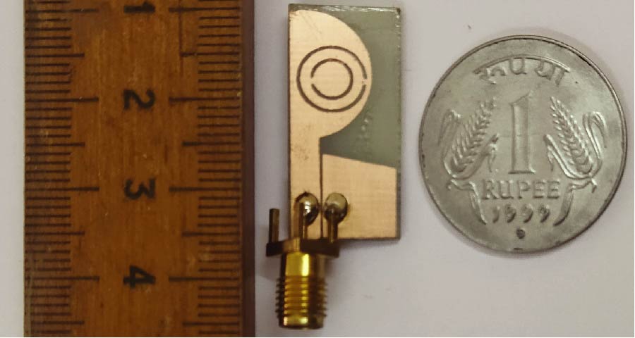
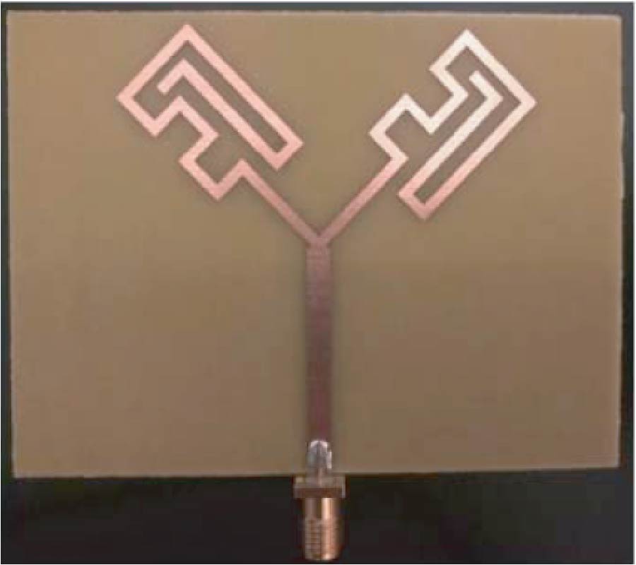
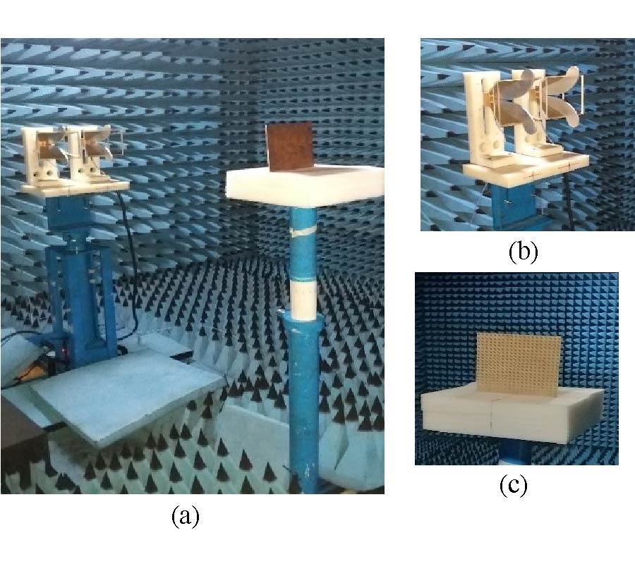
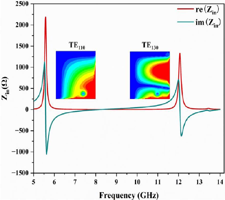
A Wideband Polarization Conversion Coding Metasurface for Monostatic Radar Cross Section Reduction of High Altitude Aerospace Platforms
E. V. Bhavya , Balamati Choudhury and Raveendranath Nair
A novel wideband cross-polarized coding metasurface has been presented in this paper towards reduction of monostatic radar cross section (RCS). A broadband reflective cross-polarization converter for linearly polarized (LP) electromagnetic waves covering both X and Ku bands has been designed for this purpose. The proposed unit cell is ultrathin (λ/15.7) and demonstrates a polarization conversion bandwidth of 10.84 GHz from 7.96 GHz to 18.8 GHz for a linearly polarized normal incidence wave which helps in reduction of radar cross section. In order to have a better understanding of cross polarization conversion (CPC), the physical mechanism of the structure has been investigated and elucidated in detail, along with the surface current distribution. The proposed structure has been studied for both transverse electric (TE) and transverse magnetic (TM) polarizations. For 1 bit coding, the suggested unit cell is utilized as the `0' bit, while the 90˚ rotated version of the unit cell is used as the `1' bit. A 4 × 4 matrix is built, and 16 configurations are explored. These combinations are known as the 2 × 2 metasurface sub-blocks, and they are used to build 200 × 200 components with size of 180 mm × 180 mm. The RCS simulation studies have been carried out from 2 to 30 GHz, and the proposed design shows a 10 dB RCS reduction from 10 GHz to 20 GHz. The scattering pattern of the suggested metasurface is comprehensively analyzed at 10 GHz, 15 GHz, and 18 GHz and demonstrates diffuse scattering in the other direction, minimizing the forward scattering RCS. The designed structure of 2.4 mm thickness has been fabricated and measured in the X and Ku bands. The measured results are in good agreement with simulated ones. In order to show the efficiency of the proposed coding metasurface, monostatic RCS estimation of the wing and body sections of high altitude aerospace paltforms (HAPS) has been simulated, and a 14.32 dB reduction has been observed over the body cross section.
A WIDEBAND POLARIZATION CONVERSION CODING METASURFACE FOR MONOSTATIC RADAR CROSS SECTION REDUCTION OF HIGH ALTITUDE AEROSPACE PLATFORMS
2022-09-08
PIER C
Vol. 123, 253-262
A Ku-Band Low-Profile Dual Circularly Polarized Antenna Based on QMSIW
Jingchun Zhai , Wen Wang , Cheng Chang , Yiqing Liu , Luzhen Wang and Zhuopeng Wang
In this paper, a low-profile dual circularly polarized (CP) antenna for Ku band satellite communication is proposed. A quarter-mode SIW (QMSIW) is designed as a circular polarization unit, which realizes circular polarization by using high-order mode TE130, and a pair of units are combined to form the antenna proposed in this paper. Feeding different units can realize left-handed circular polarization and right-handed circular polarization, respectively. The antenna impedance bandwidth is 5.66 GHz (15.16 GHz-20.82 GHz); the circular polarization bandwidth (CPBW) is 540 MHz (15.64 GHz-16.18 GHz); and the gain in the passband is 5.1 dBi, with a minimum axial ratio (AR) of 1 dB. The thickness of the antenna is only 1.5 mm, which has obvious low-profile characteristics.
A Ku-band Low-profile Dual Circularly Polarized Antenna Based On QMSIW
2022-09-08
PIER M
Vol. 113, 47-58
3D Printed Extended Lens as a Button Antenna for off -Body Links at 60 GHz
Shakti Singh Chauhan , Mahesh Pandurang Abegaonkar , Ananjan Basu and Djuradj Budimir
This paper presents a 3D printed extended hemispherical lens antenna for Body Centric Communications in 60 GHz band. The prototype consists of a 3D printed lens made of Polylactic Acid with three planar broadside patch antenna elements used as a source for the lens. The direction of the main beam antenna is switched by changing the excitation of source elements. The measured overlapping impedance bandwidth of the fabricated antenna is from 57.27 GHz to 60 GHz with reflection coefficient better than -10 dB. The main beam direction switches in broadside direction with 3 dB angular coverage from -29.2° to +30° by changing the radiating elements at 60 GHz. The measured gain is 15.28 dBi at 60 GHz. The beam switching capabilities and high gain with broadside radiation characteristics make the proposed antenna a suitable candidate for off-body links at 60 GHz. The effect of placing the antenna structure over the body is also studied in this paper. The body to off-body link measurement is successfully demonstrated with extended lens over the body and an open-ended waveguide as an external node.
3D PRINTED EXTENDED LENS AS A BUTTON ANTENNA FOR OFF-BODY LINKS AT 60 GHZ
2022-09-05
PIER C
Vol. 123, 237-251
Design of Ultra-Wideband MIMO Antenna with Dual Band Elimination Characteristics and Low Mutual Coupling
Ravindra Subhash Bakale , Anil Nandgaonkar , Shankar B. Deosarkar and Mahesh Munde
The paper proposes the design of an ultra-wideband MIMO antenna with low mutual coupling and dual-band elimination characteristics. The proposed structure consists of a microstrip-fed monopole antenna with a stub to enhance the isolation for ultra-wideband applications. The dual rejection bands corresponding to WiMAX and WLAN frequencies are designed using electromagnetic band-gap structures of mushroom-type and placed close to the microstrip transmission line of the designed antenna. The isolation enhancement of |S21| > 20 dB is achieved over the impedance bandwidth by adding two counter-facing F-pattern stubs to the ground. The impedance bandwidth of 9 GHz (2.65-11.65 GHz) for VSWR < 2.13 with the notch bands of 3.6-4.2 GHz and 5.15-5.87 GHz is obtained. The diversity gain, correlation coefficient, radiation pattern, TARC, and peak gain are also studied in the paper. The simulated and measured results are in close agreement with each other. Therefore, the proposed structure is a potential candidate for wireless communication.
DESIGN OF ULTRA-WIDEBAND MIMO ANTENNA WITH DUAL BAND ELIMINATION CHARACTERISTICS AND LOW MUTUAL COUPLING
2022-09-05
PIER C
Vol. 123, 227-236
Development of a Low Profile Wideband SIW Cavity-Backed I-Shaped Slot Antenna
Anil Kumar Katta and Praveen Babu Choppala
In this paper, a bandwidth improvement technique in substrate integrated waveguide (SIW) slotted antennas is presented. Here, wideband is achieved by using a single cavity mode (TE210) instead of multiple cavity modes, which is the most distinct approach as compared to other SIW based antennas. When the rectangle slot is loaded at bottom surface of the cavity, the TE210 cavity mode of the antenna is perturbed. As a result, two independent modes namely odd TE210 and even TE210 are successfully generated and merged in close proximity. Consequently, an impedance bandwidth of 12.8% is obtained. When a vertical slit is added at each end of the rectangle slot to make as an I-shaped slot, the impedance bandwidth is increased from 12.8% to 13.94%. The fabricated antenna shows the measured impedance bandwidth of 14.4% andexhibits a gain of 5 dBi to 7 dBi throughout the operating band. The proposed design still retains many features such as light weight, easy fabrication, and easy integration.
Development of a Low Profile Wideband SIW Cavity-backed I-shaped Slot Antenna
2022-09-02
PIER C
Vol. 123, 213-226
A Compact UWB DRA MIMO Antenna Realizing Band Notch Characteristics and Fractal Inspired Isolation Mechanism
Anindita Bhattacharjee , Anirban Karmakar and Anuradha Saha
In this communication, a new compact UWB dual port multiple-input multiple-output (MIMO) antenna is presented for wireless application. The design utilizes the property of dielectric resonator to achieve a bandwidth that ranges from 3.1 GHz to 18.5 GHz. The design has a compact size of 19×30×0.8 mm3. It consists of two rectangular shape monopole antenna elements with rectangular dielectric resonators sharing a similar ground plane. On the ground plane, a modified Hilbert curve with a meander line parasitic element was introduced to improve isolation between radiating elements which reduces mutual coupling issues. A band notch is achieved at WLAN band (5.09-5.8 GHz) by etching a pair of L-shape slots on each radiator. The gain of the antenna drops significantly at the centre of the notch band which indicates good interference suppression. Results show that the designed antenna provides a wide impedance bandwidth (below -10 dB) throughout the operating band of 3.1-18.5 GHz (142.6%). The antenna also produces nearly -20 dB isolation for the entire operating band. Results show that the simulated characteristics are in good agreement with the measured counterpart.
A COMPACT UWB DRA MIMO ANTENNA REALIZING BAND NOTCH CHARACTERISTICS AND FRACTAL INSPIRED ISOLATION MECHANISM
2022-09-02
PIER C
Vol. 123, 197-212
A Foam-Based Compact Flexible Wideband Antenna for Healthcare Applications
Kailash Vaijinath Karad and Vaibhav S. Hendre
In recent times, the study of flexible wireless devices has attracted ample attention in the fields of biomedicine and healthcare. Biomedical systems are becoming more popular and employed to find harmful elements within human bodies. A portable biomedical device makes use of a contacting or non-contacting way to find tumours inside the human body. In view of this, a compact two-slot hexagonal shape flexible wideband microstrip antenna for healthcare application is presented. The proposed antenna is designed using a low-cost, light-weight, and broadly accessible flexible foam material. The slots incorporated into the geometry have enriched the percentage bandwidth of 106.67% with a total gain of 4.67 dBi. The flexible wideband antenna of dimension 28×26×2 mm3 is fabricated using copper foil. The designed and fabricated antenna operates over the frequency of 2.94 to 9.66 GHz resulting in three different resonating frequencies; 3.8 GHz, 6.7 GHz, and 9.1 GHz. The flexible antenna is tested under different bending conditions and obtains good performance to substantiate flexibility. The Specific Absorption Rate (SAR) analysis is also performed over a three-layer tissue equivalent body model and observes a maximum SAR value of 1.9 W/Kg less than the safety limit of 2 W/Kg for 10 gm of tissue. A good agreement is observed between the simulated and measured results of the proposed antenna for free space and human proximity.
A FOAM-BASED COMPACT FLEXIBLE WIDEBAND ANTENNA FOR HEALTHCARE APPLICATIONS
2022-09-01
PIER M
Vol. 113, 35-45
A Microwave Displacement Sensor Based on SIW Double Reentrant Cavity with Ring Gaps
Jixu Ma , Yukang Chen and Jie Huang
In this study, a double reentrant cavity sensor (DRECS) loaded with ring gaps is proposed to characterize the displacement that the metal plate is inserted into the DRECS. The conventional substrate-parasitic-capacitance of DRECS in the substrate integrated waveguide (SIW) configuration, which has no contribution to the sensitivity, is successfully eliminated by using a symmetric double reentrant cavity. The ring gaps are introduced in SIW DRECS to effectively suppress the fringe electric field around the post, and enlarge the range of displacement measurements. Additionally, a displacement model, which is characterized by the quantitative relationship between the resonant frequency of DRECS and insertion depth inside DRECS, is theoretically established with the help of the electric field distribution and the equivalent circuit of the DRECS. A prototype of the designed sensor is fabricated and measured. The sensor work at 1.5-3.1 GHz and the measured results are in good agreement with the simulated ones from the displacement model. The measurement results indicate that the sensor has a displacement test range of 27 mm and Q-factor of over 150, and can achieve high sensitivity of 58 MHz/mm.
A Microwave Displacement Sensor Based on SIW Double Reentrant Cavity with Ring Gaps
2022-09-01
PIER M
Vol. 113, 23-33
Frequency Switchable and Tunable Negative Group Delay Circuits Based on Defected Microstrip Structures
Chithra Liz Palson , Rema Kunhikrishnan Sreelal , Deepti Das Krishna and Babita Roslind Jose
Group delay distortions are critical for high quality transmissions in today's communication system. In this paper, we have proposed design and analysis of defected microstrip line-based Negative Group Delay Circuits (NGDCs) to compensate for group delay distortions. Initially, a tunable pulse shaped defection based NGD structure is designed wherein a variable resistor connection allows group delay tunability. The proposed design is able to generate a group delay (GD) tuning from 0 to -4.8 ns at 2.7 GHz as the resistance is varied from 1 kΩ to 1 MΩ. Further, we embedded two stubs to implement the switchable multi-band feature on the proposed NGDC design. The NGDCs are fabricated, and the measured results confirm the proposed concept. Lastly, we designed a tunable compact NGDC with inverted-U stubs inscribed inside a microstrip line. It generated GD tunability at different frequency bands with the aid of a variable resistor and switched the frequencies as required.
Frequency Switchable and Tunable Negative Group Delay Circuits based on Defected Microstrip Structures
2022-09-01
PIER Letters
Vol. 106, 75-80
Miniaturized Lumped-Element LTCC Quadrature Hybrid with LC Stacked Structure
Jixi Lu , Jiyi Bian and Bo Zhou
A miniaturized lumped-element quadrature hybrid with a high density stacked structure is proposed in a 24-layer low temperature co-fired ceramic (LTCC) substrate. Stacking vertical-interdigital-capacitors (VICs) and vertically-spiral-inductors are for an entire size reduction. The transition between inductors realized in the inner space of the inductor further improves the utilization of three-dimensional space. The overall size of the quadrature hybrid is only 10.1×3.8×2.4 mm, or equivalently 0.0040×0.0015×0.0009λg3, which achieves a size reduction of 30.2%. Meanwhile, the proposed hybrid operates at 60 MHz with a fractional bandwidth (FBW) of 33.3%. The measured S11, S21, S31 and S41 are -14.5, -3.8, -3.7, and -14.2 dB within the operating frequency band, respectively, and both of the low phase imbalance and amplitude imbalance are achieved.
Miniaturized Lumped-element LTCC Quadrature Hybrid with LC Stacked Structure
2022-08-31
PIER M
Vol. 113, 11-22
Focusing of the Electromagnetic Field in Several Given Areas of Space
Denis Iuzvik and Maksim Stepanov
The article describes the problem of spatial separation of devices operating in the same frequency range. The possibility of focusing electromagnetic fields in several specified regions of space is considered. The proposed method for focusing the electromagnetic field can be an additional method for separation devices that operate in the same frequency range. The system under consideration, consisting of space, radiating antennas and focusing points, is represented as an abstract multipole with the number of inputs equal to the number of radiating antennas and with a set of outputs equal to the number of focusing points. A coordinate system has been introduced that makes it possible to calculate the distances between radiation and focusing points. A method for calculating complex transmission coefficients between emission points and reception points is described. An analytical expression is obtained, a system of linear algebraic equations, which makes it possible to calculate the necessary amplitudes and phases of signals supplied to radiating antennas. A model in a computer-aided design system containing 56 radiating antennas is presented. 9 focus points were set, and 4 of them should have maxima of the electromagnetic field. The simulation confirmed the theoretical calculations. A method for optimizing the calculations of the initial amplitudes and phases by eliminating the elements of the characteristic matrix is considered. This made it possible to reduce the number of elements in the characteristic matrix.
Focusing of the Electromagnetic Field in Several Given Areas of Space
2022-08-31
PIER M
Vol. 112, 243-253
A Miniaturized Wideband Wilkinson Power Divider for IoT Sub-GHz Applications
Shaimaa Abdelaziz Mahmoud Osman , Mohamed S. El-Gendy , Hadia El-Hennawy and Esmat A. F. Abdallah
This paper presents a single stage 2-way Wilkinson Power Divider (WPD) suitable for Internet of Things (IoT) low frequency applications in the band from 200 MHz to 1 GHz. It is realized using a meandered line, and an open shunt stub matching network is added to get a compact structure. Moreover, a Vertical Periodic Defected Ground Structure (VPDGS) is added below each arm in order to improve the performance at the center frequency without adding extra length to the divider. The size of the proposed power divider is 30 × 15.3 mm2 (0.082λg × 0.041λg). The fabricated power divider achieves a fractional bandwidth of 107%, an input return loss of better than 10 dB, an output return loss of 20 dB, an isolation of better than -10 dB and maximum exceeded insertion loss of 0.9 dB. The proposed compact power divider is implemented on Rogers RT/ Duroid 5880 with thickness 0.254 mm in order to bend on any conformal surface.
A Miniaturized Wideband Wilkinson Power Divider for IoT sub-GHz Applications
2022-08-31
PIER Letters
Vol. 106, 67-74
An Electrically Small All Metallic Probe-Fed Antenna for NavIC Applications
Prasanna Kushal Kumar , Gulur Sadananda Karthikeya and Prabhakar Parimala
In this paper, a novel all-metallic probe-fed antenna is proposed for L5, L1, and S bands for Navigation with Indian Constellation (NavIC) applications, and it can be used for tracking applications. The proposed antenna dimensions are 30 mm x 80 mm x 8 mm (0.11λ x 0.31λ x 0.03λ) electrical size calculated at 1176.45 MHz (L5). The radiating plane has a comb like structure where there are 8 slots which are of identical size 24 mm x 1 mm and a short slot with 6 mm x 1 mm. The ground plane is 30 mm offset with respect to the radiating plane (top plane). Usually, a high dielectric substrate antenna can resonate at lower frequencies keeping the size of the antenna electrically small, but without substrate the proposed antenna resonates at lower frequencies keeping the antenna size electrically small. The proposed design is electrically compact and economical, and the dielectric loss in the antenna is zero as the antenna is designed with copper alone, which gives a strong impression that a substrate free antenna can resonate at lower frequencies. So, from this method it can also make the antenna light weight.
AN ELECTRICALLY SMALL ALL METALLIC PROBE-FED ANTENNA FOR NAVIC APPLICATIONS
2022-08-30
PIER C
Vol. 123, 181-196
Statistical Analysis of Diffraction Loss in Outdoor Urban Microcells for 5G/6G Millimeter Wave Communications
Abdelbasset Bedda Zekri and Riadh Ajgou
Millimeter-wave (mmWave) frequencies are considered as candidate bands for 5G/6G mobile networks. Diffraction models are significant for predicting non-line-of-sight (NLOS) wireless channels while it is shown that the line of sight (LOS) path is usually blocked by buildings in urban area environments. A lot of investigations on the diffraction loss have been performed, and most of them just considered a one obscuring object and a short propagation distance. In this paper, we conduct a statistical analysis of the diffraction loss in the outdoor NLOS in Urban Micro Cell, considering a transmitter (TX) and a receiver (RX) which are located at an aggregation point on the roof of a building. We have focused on analyzing the diffraction loss suffered by mmWave signals when they hit one or two obscuring points located over rooftop of the buildings. The objects have different heights located at various distances between TX and RX. We have considered the bands: 28 GHz, 38 GHz, 60 GHz, 73 GHz and 100 GHz. The analysis is based on the diffraction model named the Knife Edge Diffraction (KED). We have strictly followed the ITU Recommendations ITU-R P.526-15 (10/2019). In this work, we use two schemes that characterize the KED model, namely Single KED (SKED) and Double Isolated KED (DIKED). Different scenarios are performed by varying different parameters of the channel between TX and RX. The results show that the diffraction loss is inversely proportional to the distance between the obscuring object and the transmitter, the wavelength, and the distance between the TX and RX.
STATISTICAL ANALYSIS OF DIFFRACTION LOSS IN OUTDOOR URBAN MICROCELLS FOR 5G/6G MILLIMETER WAVE COMMUNICATIONS