Vol. 37
Latest Volume
All Volumes
PIERC 148 [2024] PIERC 147 [2024] PIERC 146 [2024] PIERC 145 [2024] PIERC 144 [2024] PIERC 143 [2024] PIERC 142 [2024] PIERC 141 [2024] PIERC 140 [2024] PIERC 139 [2024] PIERC 138 [2023] PIERC 137 [2023] PIERC 136 [2023] PIERC 135 [2023] PIERC 134 [2023] PIERC 133 [2023] PIERC 132 [2023] PIERC 131 [2023] PIERC 130 [2023] PIERC 129 [2023] PIERC 128 [2023] PIERC 127 [2022] PIERC 126 [2022] PIERC 125 [2022] PIERC 124 [2022] PIERC 123 [2022] PIERC 122 [2022] PIERC 121 [2022] PIERC 120 [2022] PIERC 119 [2022] PIERC 118 [2022] PIERC 117 [2021] PIERC 116 [2021] PIERC 115 [2021] PIERC 114 [2021] PIERC 113 [2021] PIERC 112 [2021] PIERC 111 [2021] PIERC 110 [2021] PIERC 109 [2021] PIERC 108 [2021] PIERC 107 [2021] PIERC 106 [2020] PIERC 105 [2020] PIERC 104 [2020] PIERC 103 [2020] PIERC 102 [2020] PIERC 101 [2020] PIERC 100 [2020] PIERC 99 [2020] PIERC 98 [2020] PIERC 97 [2019] PIERC 96 [2019] PIERC 95 [2019] PIERC 94 [2019] PIERC 93 [2019] PIERC 92 [2019] PIERC 91 [2019] PIERC 90 [2019] PIERC 89 [2019] PIERC 88 [2018] PIERC 87 [2018] PIERC 86 [2018] PIERC 85 [2018] PIERC 84 [2018] PIERC 83 [2018] PIERC 82 [2018] PIERC 81 [2018] PIERC 80 [2018] PIERC 79 [2017] PIERC 78 [2017] PIERC 77 [2017] PIERC 76 [2017] PIERC 75 [2017] PIERC 74 [2017] PIERC 73 [2017] PIERC 72 [2017] PIERC 71 [2017] PIERC 70 [2016] PIERC 69 [2016] PIERC 68 [2016] PIERC 67 [2016] PIERC 66 [2016] PIERC 65 [2016] PIERC 64 [2016] PIERC 63 [2016] PIERC 62 [2016] PIERC 61 [2016] PIERC 60 [2015] PIERC 59 [2015] PIERC 58 [2015] PIERC 57 [2015] PIERC 56 [2015] PIERC 55 [2014] PIERC 54 [2014] PIERC 53 [2014] PIERC 52 [2014] PIERC 51 [2014] PIERC 50 [2014] PIERC 49 [2014] PIERC 48 [2014] PIERC 47 [2014] PIERC 46 [2014] PIERC 45 [2013] PIERC 44 [2013] PIERC 43 [2013] PIERC 42 [2013] PIERC 41 [2013] PIERC 40 [2013] PIERC 39 [2013] PIERC 38 [2013] PIERC 37 [2013] PIERC 36 [2013] PIERC 35 [2013] PIERC 34 [2013] PIERC 33 [2012] PIERC 32 [2012] PIERC 31 [2012] PIERC 30 [2012] PIERC 29 [2012] PIERC 28 [2012] PIERC 27 [2012] PIERC 26 [2012] PIERC 25 [2012] PIERC 24 [2011] PIERC 23 [2011] PIERC 22 [2011] PIERC 21 [2011] PIERC 20 [2011] PIERC 19 [2011] PIERC 18 [2011] PIERC 17 [2010] PIERC 16 [2010] PIERC 15 [2010] PIERC 14 [2010] PIERC 13 [2010] PIERC 12 [2010] PIERC 11 [2009] PIERC 10 [2009] PIERC 9 [2009] PIERC 8 [2009] PIERC 7 [2009] PIERC 6 [2009] PIERC 5 [2008] PIERC 4 [2008] PIERC 3 [2008] PIERC 2 [2008] PIERC 1 [2008]
2013-02-28
PIER C
Vol. 37, 249-259, 2013
download: 326
GPS Antenna with Metallic Conical Structure for Anti-Jamming Applications
Yoon-Ki Cho , Hee-Do Kang , Se-Young Hyun and Jong-Gwan Yook
This paper presents a cost effective and simple anti-jamming method for global positioning system (GPS) antennas in the GPS L1 (1.563-1.587 GHz) band. The proposed structure is composed of a metallic conical structure with a microstrip patch antenna, which is selected as the basic element. To overcome intentional jamming signals coming from low elevation angles, the structure is applied around the low profile patch antenna. It is found that the maximum anti-jamming performance is achieved when the lower diameter (l), height (h), and upper diameter (d) of the structure are 90, 190, and 380 mm, respectively. The experimental results show that the peak gain in the horizontal plane for the jamming signal decreases by about 6.2 dB from -6.16 to -12.36 dBic, while the peak gain in the vertical plane for the GPS signal increases by about 5.58 dB from 1.32 to 6.9 dBic. Moreover, it is shown that an improvement in the circular polarization (CP) characteristics is also obtained with the proposed structure. The measured fractional bandwidth is about 3.7% (1.561-1.62 GHz).
GPS ANTENNA WITH METALLIC CONICAL STRUCTURE FOR ANTI-JAMMING APPLICATIONS
2013-02-26
PIER C
Vol. 37, 235-248, 2013
download: 243
A Circular Fractal UWB Antenna Based on Descartes Circle Theorem with Band Rejection Capability
Rowdra Ghatak , Balaka Biswas , Anirban Karmakar and Dipak Poddar
A novel planar circular Apollonian fractal shaped UWB monopole antenna with band rejection capability is presented in this paper. The antenna performs satisfactorily in the frequency range 1.8-10.6 GHz which gives a wide impedance bandwidth of 142% for VSWR within 2. The proposed antenna has the capability to reject the frequency band 5.125-5.825 GHz assigned for IEEE802.11 a and HIPERLAN/2. This is achieved by a pair of narrow band resonant L-shaped slots in the CPW ground plane. The antenna exhibits satisfactory omnidirectional radiation characteristics throughout its operating band. The measured peak gain varies from 2 dBi to 6 dBi in the entire UWB band except the notch band. The performances of time domain characteristic is satisfactory with a group delay variation of 1 ns that shows the antenna is non dispersive. To ensure the usefulness of the proposed antenna in pulse communications systems, the correlation between the time-domain transmitting antenna input signal and the receiving antenna output signal is calculated. This antenna can be effectively used for medical imaging and military radar system along with other common UWB applications.
A CIRCULAR FRACTAL UWB ANTENNA BASED ON DESCARTES CIRCLE THEOREM WITH BAND REJECTION CAPABILITY
2013-02-18
PIER C
Vol. 37, 223-233, 2013
download: 288
Aperture and Mutual Coupled Cylindrical Dielectric Resonator Antenna Array
Affan Aziz Baba , Mohd Azman Zakariya , Zuhairi Baharudin , Mohd Haris Md Khir , Muhd. Zaka ur Rehman , Zainal Arrifin Ahmad and Yazeed Mohammad A. Qasaymeh
A 1 x 3 element linear array using cylindrical dielectric resonator antennas (CDRAs) is designed and presented for 802.11a WLAN system applications. The top and bottom elements of CDRA array are excited through the rectangular coupling slots etched on the ground plane, while the slots themselves are excited through the microstrip transmission line. The third element (i.e., central CDRA) is excited through the mutual coupling of two radiating elements by its sides. This mechanism enhances the bandwidth (96.1%) and gain (14.3%) as compared to aperture coupled technique. It is also observed that the side lobe levels are reduced over the designed frequency band. Using CST microwave studio, directivity of 10.5 dBi has been achieved for operating frequency of 5.6 GHz. Designed antenna array is fabricated and tested. Simulated and measured results are in good agreement. The equivalent lumped element circuit is also designed and presented using Advanced design system (ADS) for this proposed array.
APERTURE AND MUTUAL COUPLED CYLINDRICAL DIELECTRIC RESONATOR ANTENNA ARRAY
2013-02-18
PIER C
Vol. 37, 211-221, 2013
download: 274
Design of Novel UWB Slot Antenna for Bluetooth and UWB Applications
Liang Xu , Bin Yuan and Shuang He
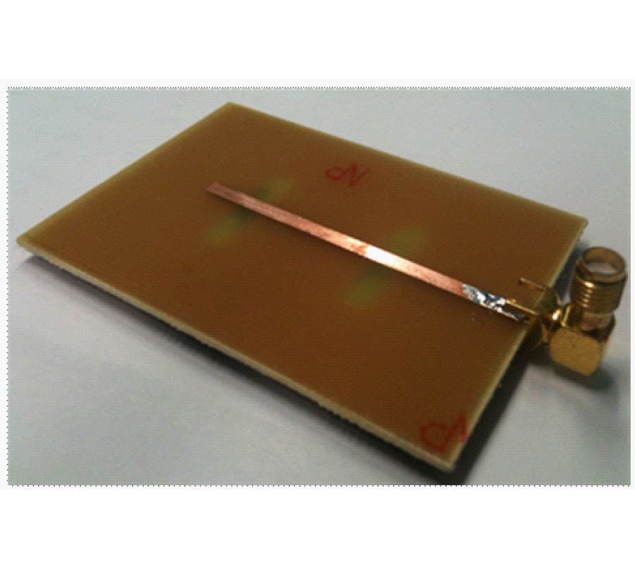
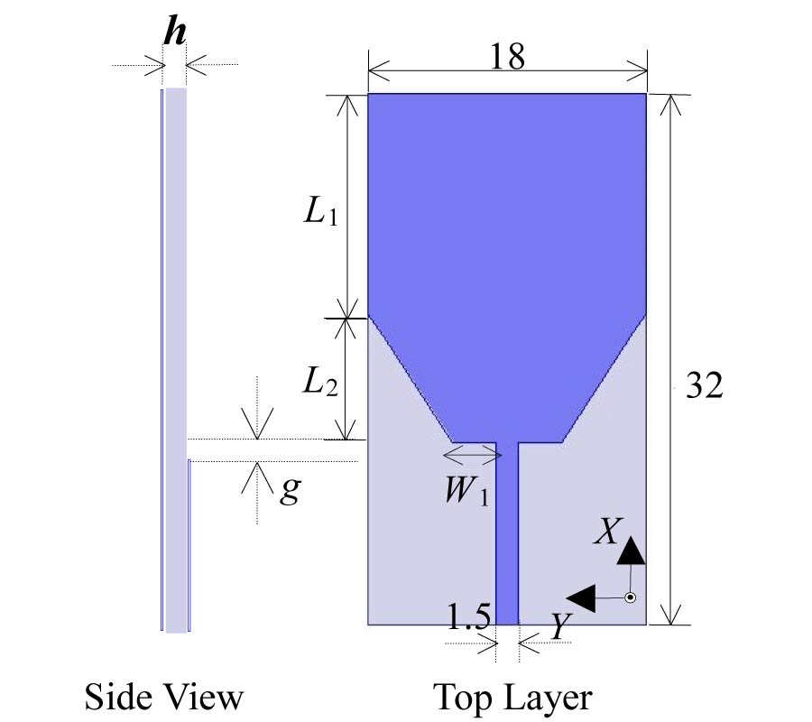
In this article, a novel wideband planar monopole antenna for applications in 2.4 GHz Bluetooth and UWB bands is presented and investigated. The low-profile antenna comprises an approximate rectangle patch for covering the UWB band (3.1~10.6 GHz). A lower pass band, 2.4 GHz Bluetooth band (2.4~2.484 GHz), can be realized by adding a pair of U-shaped parasitic strips bilaterally beside the feed line without affecting its UWB behavior. The proposed antenna is designed and built on a FR-4 substrate, with overall size of 18 mm×32 mm. The simulated and measured results are presented and show that the proposed compact antenna has a stable and good radiation patterns across all the relevant bands.
DESIGN OF NOVEL UWB SLOT ANTENNA FOR BLUETOOTH AND UWB APPLICATIONS
2013-02-18
PIER C
Vol. 37, 199-209, 2013
download: 222
A Comprehensive Study on Decoupling Between Inverted-F Antennas Using Slitted Ground Plane
Takeshi Fukusako and Yasuhiro Harada
A simple structure for achieving low mutual coupling between two inverted-F antennas is presented. A low coupling between the antennas can be achieved by using two slits on the ground plane. The interval between the antennas can be closer than λ/8. Furthermore, this technique can be combined with other techniques. This is good for designing small handsets which need shorter intervals between antennas. In this paper, the authors present an slitted ground structure and report analysys on the mechanism the structure, where a mutual coupling of -35 dB can be achieved using the slitted ground.
A COMPREHENSIVE STUDY ON DECOUPLING BETWEEN INVERTED-F ANTENNAS USING SLITTED GROUND PLANE
2013-02-16
PIER C
Vol. 37, 183-197, 2013
download: 240
Absolute Adaptive CS Model and Modified Strong Tracking Unscented Filter for High Maneuvering Target Tracking
Zheng Zhou , Jin-Mang Liu and Chang-Yun Liu
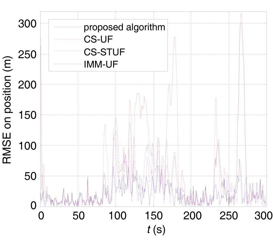
Absolute adaptive current statistical (AACS) model and modified strong tracking unscented filter (MSTUF) are proposed for maneuvering target tracking (MTT) under nonlinear measurement in this paper. The key point of the AACS model is to associate the instantaneous acceleration variance with some elements of state covariance matrix by constructing acceleration increment models of the acceleration limit and acceleration mean in the CS model, while the maneuvering frequency can adjust itself according to the change of the measurement residual. MSTUF is proposed for high maneuver tracking under nonlinear measurement by incorporating the modified strong tracking filter (STF) into the unscented filter (UF). Since the state covariance, process noise covariance and maneuvering frequency can adjust themselves jointly according to the residual, the proposed algorithm, called the AACS-MSTUF, has a good performance on both maneuver and non-maneuver. Simulation results indicate that the overall performance of the proposed algorithm is better than the interacting multiple-model unscented filter (IMM-UF), UF and original strong tracking unscented filter (STUF) based on the CS model (CS-STUF) when considering tracking accuracy, stability, convergence and computational complexity.
ABSOLUTE ADAPTIVE CS MODEL AND MODIFIED STRONG TRACKING UNSCENTED FILTER FOR HIGH MANEUVERING TARGET TRACKING
2013-02-07
PIER C
Vol. 37, 171-182, 2013
download: 451
Compact Loop Antenna for Near-Field and Far-Field UHF RFID Applications
Xiao-Zheng Lai , Ze-Ming Xie and Xuan-Liang Cen
A novel type of radio frequency identification (RFID) reader antenna is proposed for mobile ultra-high frequency (UHF) RFID device. By folded-dipole loop structure with parasitic element, a small antenna size of 31 * 31 * 1:6 mm3 is achieved. The antenna with different parasitic element size can work on different UHF RFID bands. The antenna prototype is fabricated and the measured bandwidth is around 13.5 MHz (915.5-929 MHz), which covers the China RFID Band (920-925 MHz). The measured reading distance achieves 65 mm with the near-field RFID tag and 1.17 m with the far-field tag. The measurement agrees well with simulated result and shows that antenna is desirable for both near-field and far-field UHF RFID applications.
COMPACT LOOP ANTENNA FOR NEAR-FIELD AND FAR-FIELD UHF RFID APPLICATIONS
2013-02-07
PIER C
Vol. 37, 159-170, 2013
download: 449
Construction of a 12 GHz Total Power Radio Telescope for Teaching Purposes, Suitable for Noisy Environments, Using Satellite TV Devices
Maurizio Tinti
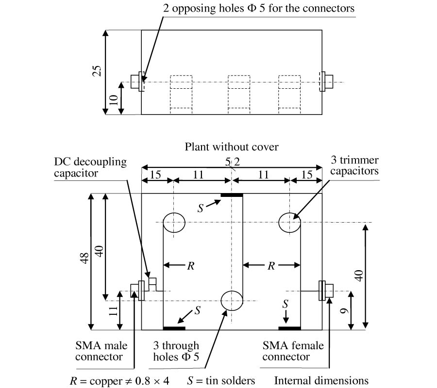
Schools and universities often need to support theoretical lectures on Radio Astronomy with practical lessons; in addition, science centres need instruments to explain this subject to the general public. However, professional radio telescopes are largely inaccessible to students and the public, because they tend to be very costly and are still fairly uncommon. It would seem, therefore, interesting to explore the possibility of designing a low-cost radio telescope for teaching purposes. The most critical part of a radio telescope is its receiver; considering the low intensity of radiation from the radio sky, this needs, among other features, to be very sensitive, necessitating the use of expensive low noise amplifiers, often cooled to low temperatures. For some time now, low-cost components for the reception of satellite TV have been available on the consumer market. These are known as Low Noise Block (LNB) and they include, as a front-end, an amplifier with very low intrinsic noise. In this study, we wanted to test the feasibility of designing and using a 12 GHz total power demonstrative radio telescope, using, as a front-end, an LNB mounted in the focus of an offset parabolic mirror. Unlike other designs, we made the system suitable for environments with high electromagnetic noise, such as schools in urban centres, by using a bandpass filter in the Intermediate Frequency section.
CONSTRUCTION OF A 12 GHZ TOTAL POWER RADIO TELESCOPE FOR TEACHING PURPOSES, SUITABLE FOR NOISY ENVIRONMENTS, USING SATELLITE TV DEVICES
2013-02-05
PIER C
Vol. 37, 145-157, 2013
download: 261
Design Filters Using Tunable E-Shaped Dual-Mode Resonators for Lower-Ultra-Wideband and Upper-Ultra-Wideband Applications
Yan-Liang Wu , Cheng Liao , Xiang-Zheng Xiong and Xuan-Ming Zhong
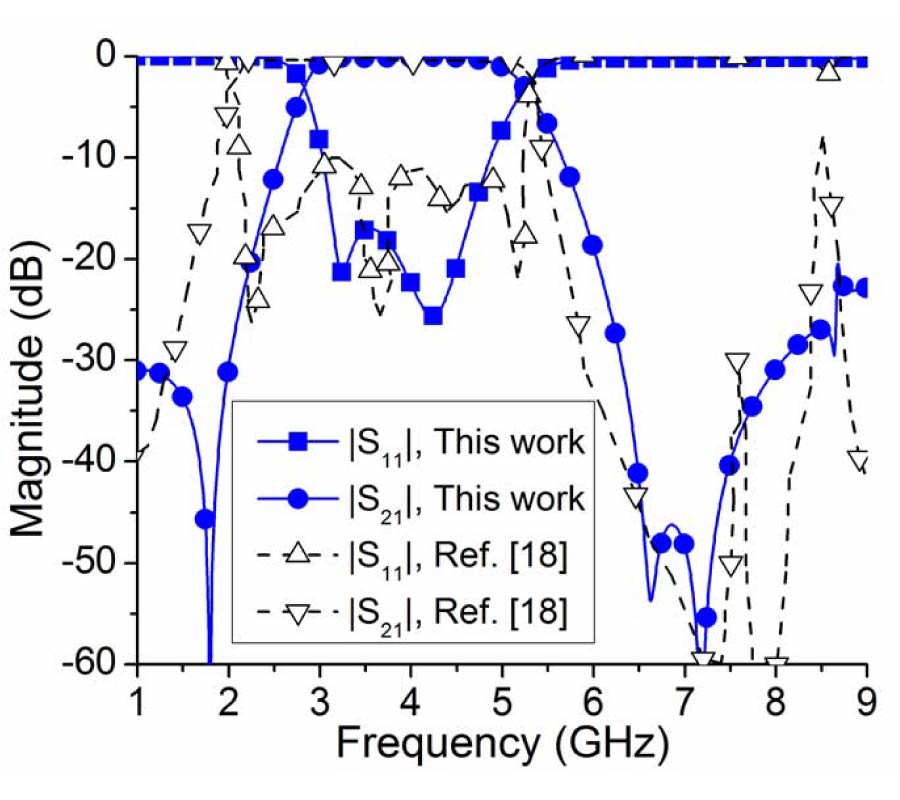
Two ultra-wideband (UWB) microstrip bandpass filters (BPFs) are proposed by using tunable E-shaped dual-mode microstrip Stepped-Impedance Resonator (SIR). For the lower band filter measurement results show there is a passband of 3.1 GHz to 5.2 GHz and its 3 dB fractional bandwidth is 51%. The UWB upper band filter may be obtained by tuning E-shaped SIR. The measurement results show there is a passband of 6 GHz to 10.6 GHz and its 3 dB fractional bandwidth is 55%. Compared with the similar investigation using the cascade of electromagnetic band gap (EBG)-embedded multiplemode resonator (MMR) and fork resonator, the proposed approach has some advantages, such as easier adjustment of bandwidths, better passband performances and smaller size etc.
DESIGN FILTERS USING TUNABLE E-SHAPED DUAL-MODE RESONATORS FOR LOWER-ULTRA-WIDEBAND AND UPPER-ULTRA-WIDEBAND APPLICATIONS
2013-02-05
PIER C
Vol. 37, 131-144, 2013
download: 388
A High-Directivity Microstrip Patch Antenna Design by Using Genetic Algorithm Optimization
Jeevani Windhya Jayasinghe , Jaume Anguera and Disala N. Uduwawala
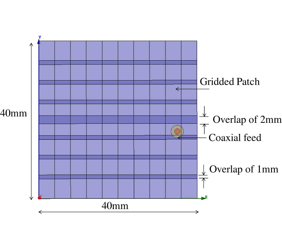
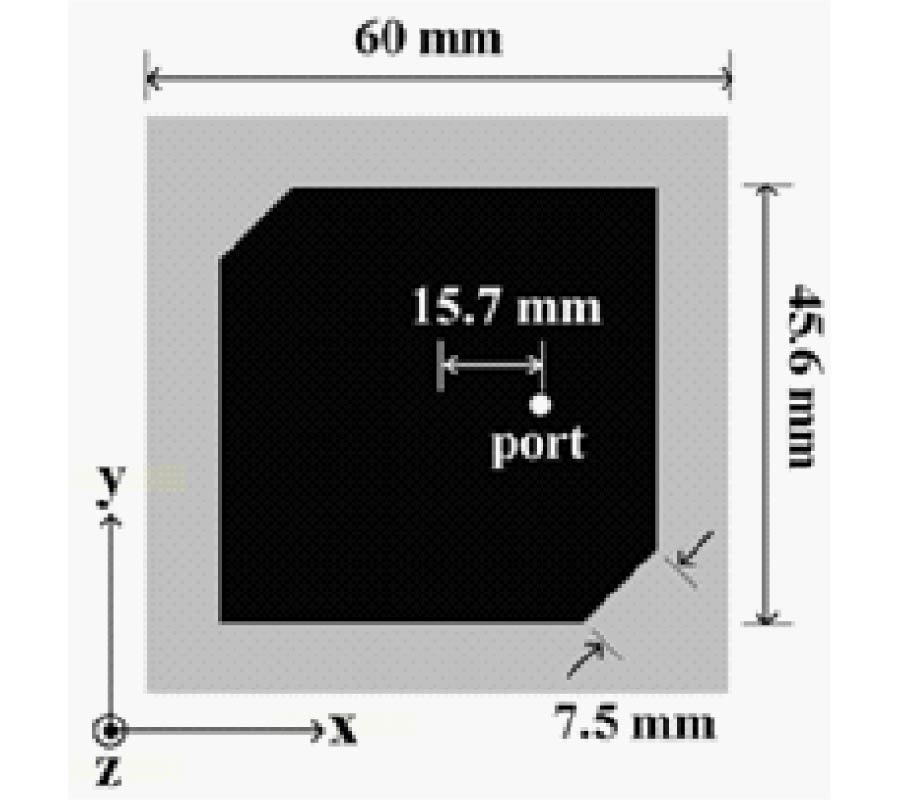
A high-directivity patch antenna with broadside directivity is attractive, since a narrow beam can be obtained without the need of using an array of antennas. Therefore, the solution becomes simpler as there is no need for a complicated feeding network. In this sense, this paper presents a novel patch antenna design with high directivity in the broadside direction by using genetic algorithms (GA). The proposed GA method divides the overall patch area into different cells taking into account that cells have a small overlap area between them. This avoids optimized geometries where cells have only an infinitesimal connection. Therefore, the proposed method is robust for manufacturing. The antenna operates in a higher-order mode at 4.12 GHz and the geometry fits inside a patch of 40 mm × 40 mm on a substrate with a relative permittivity of 3.38 and a thickness of 1.52 mm resulting in a directivity of 10.5 dBi. The specialty of this design is the use of GA to select the optimized shape and the feeding position instead of a known shape and a fixed feeding position. The antenna has been fabricated and the simulation results are in good agreement with the measurements. This results in a simpler design of a single high-directivity patch, which can substitute an array of two elements operating in the fundamental mode.
A HIGH-DIRECTIVITY MICROSTRIP PATCH ANTENNA DESIGN BY USING GENETIC ALGORITHM OPTIMIZATION
2013-02-01
PIER C
Vol. 37, 119-130, 2013
download: 235
Dual-Mode Dual-Band Bandpass Filter Based on Square Loop Resonator
Kun Deng , Shuai Yang , Shou-Jia Sun , Bian Wu and Xiao-Wei Shi
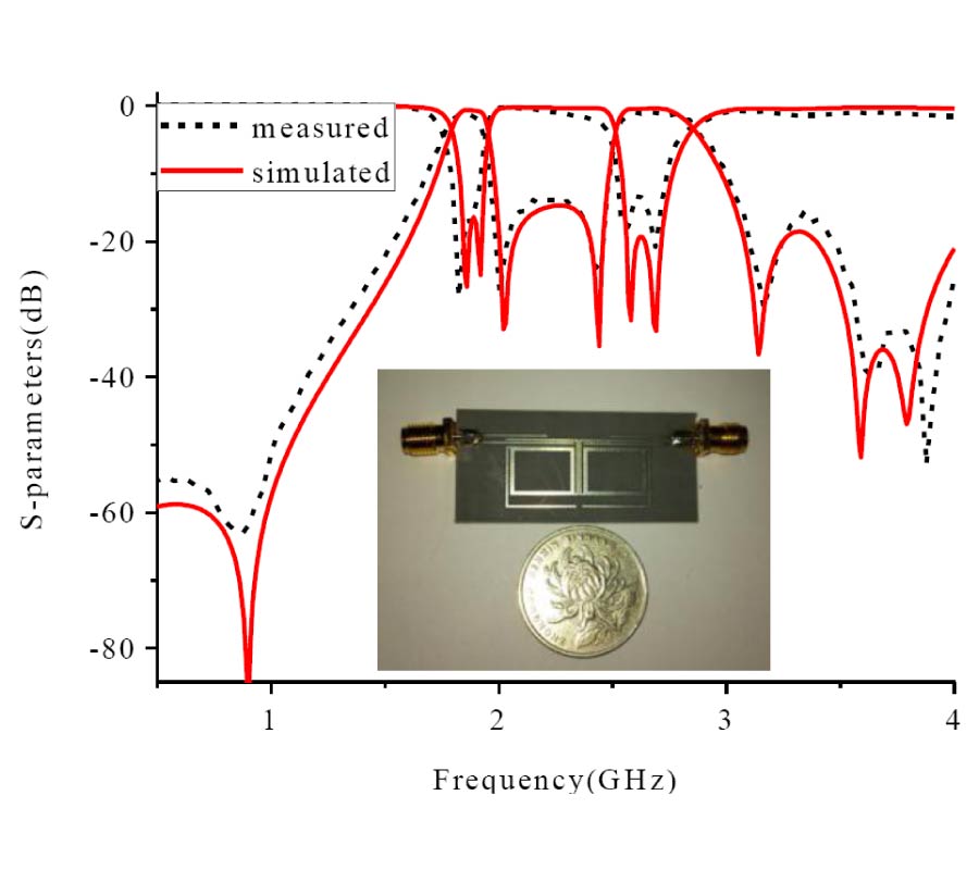
In this paper, a dual-mode dual-band microstrip bandpass filter utilizing asymmetric square loop resonators is proposed. A pair of bent open-circuited stubs is installed to the loop as perturbation stubs. By stretching the perturbation stubs more than half-wavelength of the loop, the degenerated modes in a loop are split for dual-band operation. Two asymmetric resonators are cascaded to form two bands. Even- and odd-mode analysis method is used to deduce the resonant frequencies of two bands. Based on the transmission line theory, resonant frequencies of the two resonances are derived. According to the resonant conditions, a kind of dual-mode dual-band bandpass filter can be easily designed. Finally, a dual-band filter with two bands centering at 1.9 GHz and 2.6 GHz is designed in a comprehensive way. Measured results of experimental circuit show good agreement with simulated responses.
DUAL-MODE DUAL-BAND BANDPASS FILTER BASED ON SQUARE LOOP RESONATOR
2013-02-01
PIER C
Vol. 37, 107-118, 2013
download: 302
A Dual-Band Bandpass Filter with a Tunable Passband
Ding-Hong Jia , Quanyuan Feng , Xiao-Guo Huang and Qian-Yin Xiang
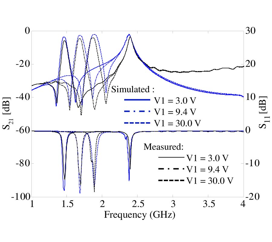
In this paper, a novel dual-band bandpass filter with a tunable passband is proposed. Based on two quarter-wavelength resonators and one half-wavelength resonator, dual-band character is designed by introducing two independent coupling paths. The filter structure is designed and can be divided into two parts. The Transmission Zeros (TZs) are derived through simulation. By varying the reverse bias voltage applied to the varactor diodes which are connected to the resonators, the first passband can be independently tuned. The second passband can be easily controlled by the width of the half-resonator. Finally, simulation results show a first tunable passband with a constant fractional-bandwidth of 3.9 ± 0.3 %, a center frequency of 1.472-1.886 GHz, and the second passband almost remains constant with a fractional-bandwidth 2.4% at frequency range 2.24 GHz. The measurement of the fabricated example shows good agreement with the simulation.
A DUAL-BAND BANDPASS FILTER WITH A TUNABLE PASSBAND
2013-01-31
PIER C
Vol. 37, 95-106, 2013
download: 244
Dual-Band Bandpass Filter Using a Single Short-Ended Dual-Mode Resonator with Adjustable First Passband
Shou Jia Sun , Shuai Yang , Bian Wu , Kun Deng and Chang-Hong Liang
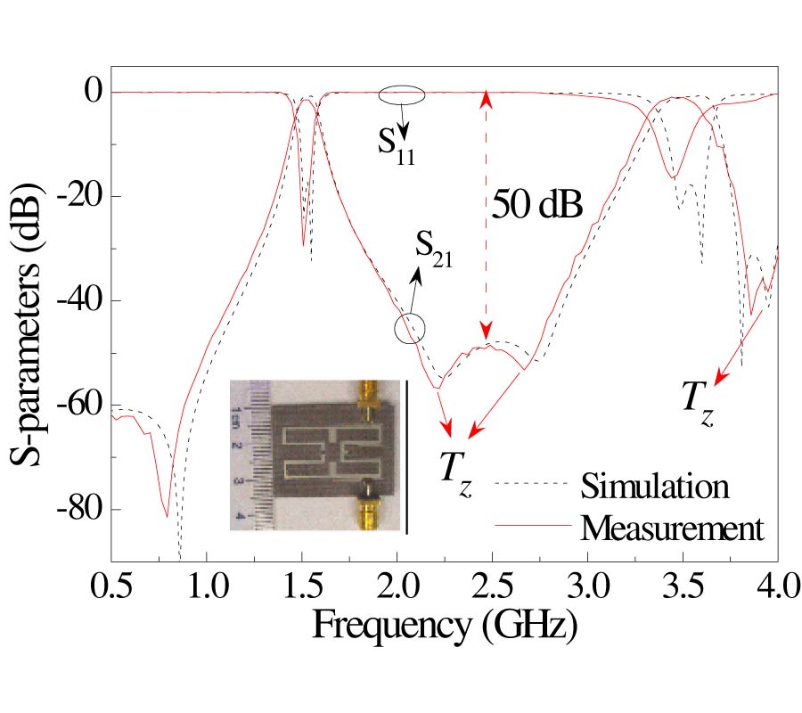
In this paper, a novel dual-band bandpass filter (BPF) based on a single short-ended dual-mode resonator (SEDMR) is presented. According to the voltage distribution of the resonator, two pairs of loaded open stubs, inside and outside of the resonator, are utilized to tune the center frequency and the external quality factor of the first passband respectively, while there is no influence on the second passband. Meanwhile, source-load coupling is introduced to produce transmission zeros to improve the passband selectivity and band-to-band isolation. For demonstration, a dual-band filter working at 1.52 GHz for GPS and 3.5 GHz for WiMax is designed, fabricated and measured with insertion losses of 1.47 and 0.95 dB. In addition, two transmission zeros, introduced by source-load coupling, located at 2.19 and 2.67 GHz between the first and second passband improve passband selectivity and band-to-band isolation better than 50 dB.
DUAL-BAND BANDPASS FILTER USING A SINGLE SHORT-ENDED DUAL-MODE RESONATOR WITH ADJUSTABLE FIRST PASSBAND
2013-01-31
PIER C
Vol. 37, 83-94, 2013
download: 455
Archimedean Spiral Antenna with Band-Notched Characteristics
Fadalia Dina Dahalan , Sharul Kamal Bin Abd Rahim , Mohamad Rijal Hamid , Muhammad Zairil Bin Muhammad Nor , Mohd Subri Bin Abdul Rani and Peter S. Hall
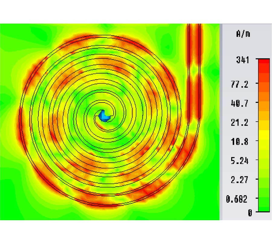
A coplanar waveguide (CPW)-fed Archimedean spiral antenna with band notched characteristics is presented for ultra-wideband (UWB) applications. The proposed antenna consists of a two-arm spiral fed by a CPW line. The novelty of this design is integrating three inverted U-shaped slots within the feeding line of the spiral antenna to introduce frequency band notched characteristics at 5.8 GHz. This antenna covers the frequency range from 3.1 GHz to 10.6 GHz with VSWR less than 2, except at a band rejection frequency of 5.8 GHz. Simulated and measured data are presented to verify the proposed design.
ARCHIMEDEAN SPIRAL ANTENNA WITH BAND-NOTCHED CHARACTERISTICS
2013-01-31
PIER C
Vol. 37, 67-81, 2013
download: 439
Design of Printed Yagi Antenna with Additional Driven Element for WLAN Applications
Jafar Ramadhan Mohammed
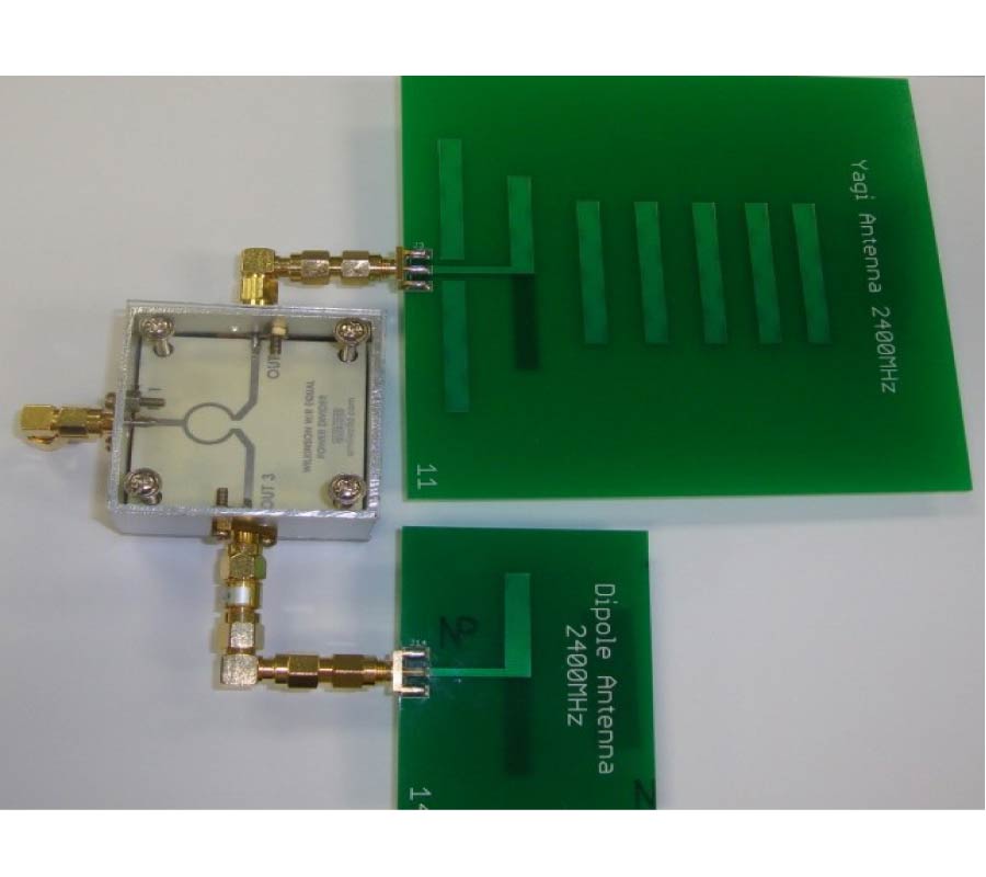
A new configuration of Yagi antenna is proposed, which can improve the forward/backward ratio (f/b) significantly while maintaining a high gain. This configuration involves the addition of one radiating element (dipole) to the original Yagi array which produces a controllable pattern used for cancellation of back lobe. This additional element may arrange on parallel (side-by-side) or collinear to a radiating dipole of the original Yagi antenna. It is shown here that the technique is most effective for collinear configuration (exhibits smaller mutual effects) and that there then exists an optimum length and position for the added element. The amplitude of the excitation of the additional element determines the angular location of the back lobe reduction. To demonstrate the major benefits, comparisons are made among the proposed and conventional Yagi configurations. Numerical and measured results of our design show more than 20 dB front to back ratio at 2.4 GHz. To the author's knowledge, this is the first printed Yagi antenna presented that has a high gain and a high f/b ratio designed using simple technique. Moreover, the proposed array represents a simple and valuable alternative to the stack Yagi antennas as the obtainable radiation characteristics are satisfactory in terms of both forward and backward gain.
DESIGN OF PRINTED YAGI ANTENNA WITH ADDITIONAL DRIVEN ELEMENT FOR WLAN APPLICATIONS
2013-01-28
PIER C
Vol. 37, 53-66, 2013
download: 268
A New Dual Band Balanced-to-Balanced Power Divider
Bin Xia and Jun-Fa Mao
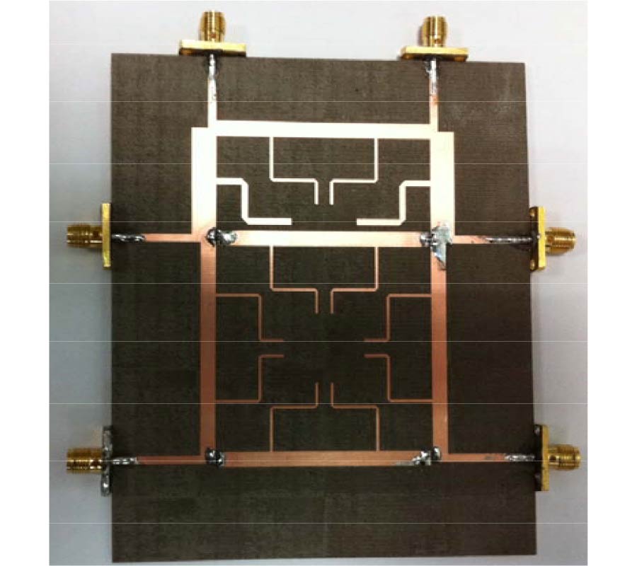
In this paper, a new dual band balanced-to-balanced power divider is proposed. By using the dual frequency 90° phase shifter based T model, the proposed balanced-to-balanced power divider can be deduced. By using the method in our previous work, the dual band balanced-to-balanced power divider could be designed with 1:1 power division. This balanced-to-balanced power divider is implemented on microstrip structure. Comparing the results calculated in analytical method with that simulated by the full-wave electromagnetic simulator, and that measured by the network analyzer, the final results show that they have a good mixed mode performance. The pass band 1 is from 2.395 GHz to 2.550 GHz, and the pass band 2 is from 5.245 GHz to 5.30 GHz. The maximum isolations for pass band 1 and pass band 2 are 17.8 dB and 17.6 dB, respectively.
A NEW DUAL BAND BALANCED-TO-BALANCED POWER DIVIDER
2013-01-24
PIER C
Vol. 37, 41-51, 2013
download: 256
A Novel Dual-Band Multi-Way Power Divider Using Coupled Lines
Lulu Bei , Shen Zhang and Kai Huang
In this paper, coupled lines are used in the design of a dual band planar multi-way Bagley polygon power divider to reduce the size is proposed. For the input port matching and transmission characters are affected by the even mode impedance only, analysis of the multi-way Bagley polygon power divider and equivalent circuit based on coupled lines, closed form design equations are presented with even mode impedance, and odd mode impedance is obtained arbitrarily. To validate the design procedure, two dual band three-way Bagley polygon power dividers are designed, simulated, and fabricated using coupled lines with areas of 3.17 cm2 and 2.53 cm2, and the corresponding conventional divider with areas of 17.86 cm2 and 11.74 cm2, respectively. When coupled lines are used, the layout is more compact with a reduction in size of more than nearly 80% compared to the conventional design.
A NOVEL DUAL-BAND MULTI-WAY POWER DIVIDER USING COUPLED LINES
2013-01-24
PIER C
Vol. 37, 29-40, 2013
download: 270
Study of the Inter-Stage Capacitor Effects of a RF CMOS Power Amplifier to Enhance Its Efficiency
Hoyong Hwang , Donghwan Seo , Jonghoon Park and Changkun Park
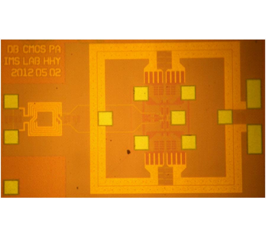
In this work, we analyze the effects of an inter-stage capacitor located between the power stage input and the driver stage output on the overall efficiency of a RF CMOS power amplifier and on gate-drain reliability problems. To verify the analyzed effects, we designed a RF CMOS power amplifier with a center frequency of 1.85-GHz. Class-D amplifiers with a feedback resistor are used as driver stages, and a class-E amplifier is used as the power stage. A distributed active transformer is adapted for use in the output power combiner for high efficiency. The inter-stage capacitor between driver and the power stage is removed to enhance the switching operation of the power stage. By eliminating the inter-stage capacitor, the supply voltage of the driver stage can be decreased compared to that in a general amplifier. Accordingly, the power-added efficiency is improved and the gate-drain reliability problems are moderated compared to a general amplifier. The analyzed effect of the inter-stage capacitor is verified successfully using the measured results of the designed amplifiers.
STUDY OF THE INTER-STAGE CAPACITOR EFFECTS OF A RF CMOS POWER AMPLIFIER TO ENHANCE ITS EFFICIENCY
2013-01-24
PIER C
Vol. 37, 15-28, 2013
download: 304
A Magneto-Inductive Link Budget for Wireless Power Transfer and Inductive Communication Systems
Johnson Ihyeh Agbinya
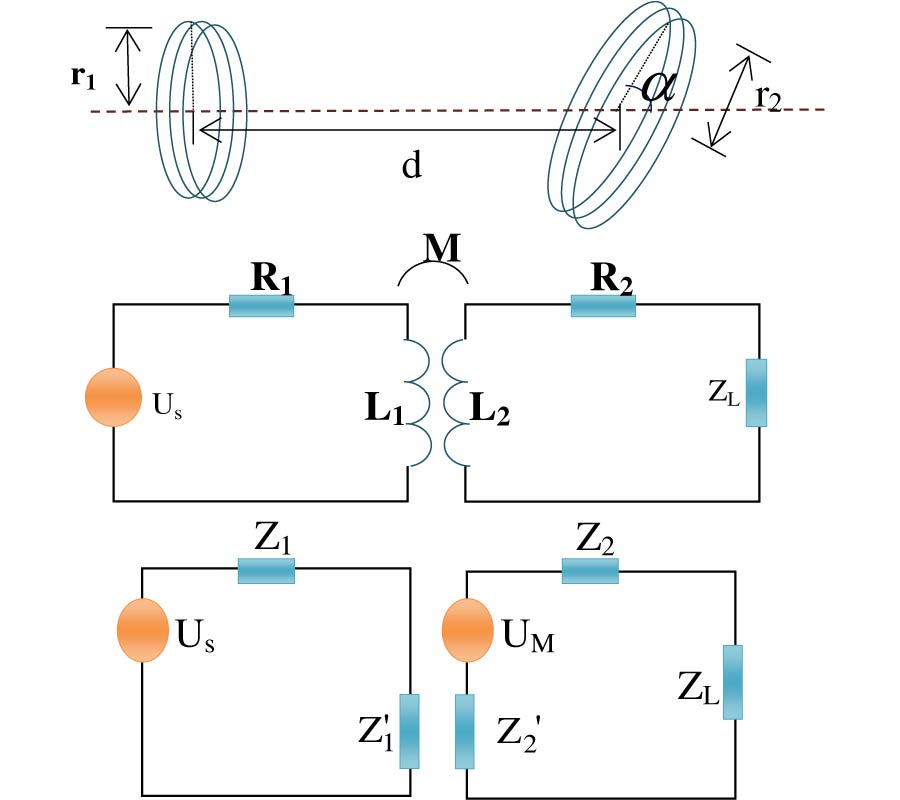
This paper presents a propagation model and inductive link budget based on link equations for chains of inductive loops as the basis for determining the link budget of an inductive communication and wireless power transfer systems. The link between the transmitter and receiver is modeled in similar format as in radio frequency systems. The transmitter antenna gain, path loss model and receiver antenna gain are also modeled for the inductive case. This allows the magnetic path loss to be estimated accurately. Also the induced receiver current due to a transmitter voltage can be computed apriori enabling efficient design of inductive links and transceivers.
A MAGNETO-INDUCTIVE LINK BUDGET FOR WIRELESS POWER TRANSFER AND INDUCTIVE COMMUNICATION SYSTEMS
2013-01-24
PIER C
Vol. 37, 1-13, 2013
download: 244
An L-Probe Fed Stacked Rectangular Microstrip Antenna Combined with a Ring Antenna for Triple Band Operation in Its
Takafumi Fujimoto and Daisuke Tanaka
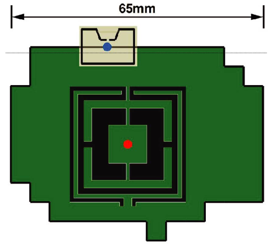
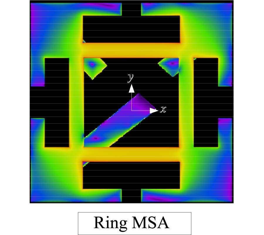
A stacked rectangular microstrip antenna with a shorting plate combined with a rectangular ring microstrip antenna is proposed for triple band operation (GPS, VICS and ETC) in ITS. The two microstrip antennas are excited by an L-probe feed. In the ETC band, axial ratio deteriorates due to asymmetrical distributions of the electric current in the ring microstrip antenna. In this paper, an approach to improve the axial ratio for ETC is also proposed. The proposed antenna has the proper radiation patterns and impedance matching for the GPS, VICS and ETC.
AN L-PROBE FED STACKED RECTANGULAR MICROSTRIP ANTENNA COMBINED WITH A RING ANTENNA FOR TRIPLE BAND OPERATION IN ITS