Vol. 118
Latest Volume
All Volumes
PIERC 142 [2024] PIERC 141 [2024] PIERC 140 [2024] PIERC 139 [2024] PIERC 138 [2023] PIERC 137 [2023] PIERC 136 [2023] PIERC 135 [2023] PIERC 134 [2023] PIERC 133 [2023] PIERC 132 [2023] PIERC 131 [2023] PIERC 130 [2023] PIERC 129 [2023] PIERC 128 [2023] PIERC 127 [2022] PIERC 126 [2022] PIERC 125 [2022] PIERC 124 [2022] PIERC 123 [2022] PIERC 122 [2022] PIERC 121 [2022] PIERC 120 [2022] PIERC 119 [2022] PIERC 118 [2022] PIERC 117 [2021] PIERC 116 [2021] PIERC 115 [2021] PIERC 114 [2021] PIERC 113 [2021] PIERC 112 [2021] PIERC 111 [2021] PIERC 110 [2021] PIERC 109 [2021] PIERC 108 [2021] PIERC 107 [2021] PIERC 106 [2020] PIERC 105 [2020] PIERC 104 [2020] PIERC 103 [2020] PIERC 102 [2020] PIERC 101 [2020] PIERC 100 [2020] PIERC 99 [2020] PIERC 98 [2020] PIERC 97 [2019] PIERC 96 [2019] PIERC 95 [2019] PIERC 94 [2019] PIERC 93 [2019] PIERC 92 [2019] PIERC 91 [2019] PIERC 90 [2019] PIERC 89 [2019] PIERC 88 [2018] PIERC 87 [2018] PIERC 86 [2018] PIERC 85 [2018] PIERC 84 [2018] PIERC 83 [2018] PIERC 82 [2018] PIERC 81 [2018] PIERC 80 [2018] PIERC 79 [2017] PIERC 78 [2017] PIERC 77 [2017] PIERC 76 [2017] PIERC 75 [2017] PIERC 74 [2017] PIERC 73 [2017] PIERC 72 [2017] PIERC 71 [2017] PIERC 70 [2016] PIERC 69 [2016] PIERC 68 [2016] PIERC 67 [2016] PIERC 66 [2016] PIERC 65 [2016] PIERC 64 [2016] PIERC 63 [2016] PIERC 62 [2016] PIERC 61 [2016] PIERC 60 [2015] PIERC 59 [2015] PIERC 58 [2015] PIERC 57 [2015] PIERC 56 [2015] PIERC 55 [2014] PIERC 54 [2014] PIERC 53 [2014] PIERC 52 [2014] PIERC 51 [2014] PIERC 50 [2014] PIERC 49 [2014] PIERC 48 [2014] PIERC 47 [2014] PIERC 46 [2014] PIERC 45 [2013] PIERC 44 [2013] PIERC 43 [2013] PIERC 42 [2013] PIERC 41 [2013] PIERC 40 [2013] PIERC 39 [2013] PIERC 38 [2013] PIERC 37 [2013] PIERC 36 [2013] PIERC 35 [2013] PIERC 34 [2013] PIERC 33 [2012] PIERC 32 [2012] PIERC 31 [2012] PIERC 30 [2012] PIERC 29 [2012] PIERC 28 [2012] PIERC 27 [2012] PIERC 26 [2012] PIERC 25 [2012] PIERC 24 [2011] PIERC 23 [2011] PIERC 22 [2011] PIERC 21 [2011] PIERC 20 [2011] PIERC 19 [2011] PIERC 18 [2011] PIERC 17 [2010] PIERC 16 [2010] PIERC 15 [2010] PIERC 14 [2010] PIERC 13 [2010] PIERC 12 [2010] PIERC 11 [2009] PIERC 10 [2009] PIERC 9 [2009] PIERC 8 [2009] PIERC 7 [2009] PIERC 6 [2009] PIERC 5 [2008] PIERC 4 [2008] PIERC 3 [2008] PIERC 2 [2008] PIERC 1 [2008]
2022-03-03
PIER C
Vol. 118, 263-275, 2022
download: 286
Miniaturized Quad-Port UWB-MIMO Antenna with Band-Notched Characteristics at 5 GHz
Qasim Hadi Kareem Al-Gertany and Malik Jassim Farhan
Small footprint of the multi-input-multi-output (MIMO) antenna is extremely desirable for space-constrained ultra-wideband (UWB) communication systems. Compact MIMO antennas with improved isolation and wide operating bandwidth are the significant subject of the work. Therefore, this paper presents a miniaturized four-port polarization diversity UWB-MIMO antenna operating in the frequency range of 3.1-12 GHz with band-notched characteristics. Four octagon-shaped radiating elements with a common ground are placed orthogonal to each other for good isolation. Band rejection features between 4.5 and 5.5 GHz were achieved by including an open-ended slot at the upper edge of the octagon-shaped antenna. The MIMO antenna was etched on a low-cost 32.3 x 32.3 x 0.8 mm3 FR-4 dielectric substrate. The antenna radiates in a quasi-omnidirectional pattern on the H-plane throughout the operational bandwidth, with higher than 15 dB isolation, low envelope correlation, and high antenna gain. As a result, this antenna is well suited for diverse applications and portable devices.
2022-03-03
PIER C
Vol. 118, 247-262, 2022
download: 444
Compact MIMO Antenna Designs Based on Hybrid Fractal Geometry for 5G Smartphone Applications
Muhannad Y. Muhsin , Ali Jabbar Salim and Jawad K. Ali
Compact low-profile four and eight elements Multi-Input Multi-Output (MIMO) antenna arrays are presented for 5G smartphone devices. The proposed antenna systems can operate at two dual-wideband with triple resonance frequencies that cover the extended Personal Communication Purposes (PCS) n25 band and other related applications, the mobile china's band, and the LTE Band-46. The proposed antenna element is designed based on modified Minkowski and Peanocurves fractal geometries. Desirable antenna miniaturization with multi-band capability is obtained by utilizing the space-filling and self-similarity properties of the proposed hybrid fractal geometries where the overall antenna size is (11.47 mm × 7.19 mm). All antennas are printed on the surface layer of the main mobile board. Based on the self-isolated property, good isolation is attained without employing additional decoupling structures and/or isolation techniques, increasing system complexity and reducing antenna efficiency. For evaluating the performance of the proposed antenna systems, the scattering parameters, antenna efficiencies, antenna gains, antenna radiation characteristics, envelope correlation coefficients (ECCs) and mean effective gains (MEGs) are investigated. The performances are evaluated to confirm the suitability of the proposed MIMO antenna systems for 5G mobile terminals. The proposed eight elements MIMO system has been fabricated and tested. The measured and simulated results are in good agreement.
2022-03-02
PIER C
Vol. 118, 231-245, 2022
download: 186
Wide-Band Directional Cavity Antenna with Low Scanning Loss for WLAN
Somanatha Pai Swapna , Gulur Sadananda Karthikeya , Shiban Kishen Koul and Ananjan Basu
In this paper, a wide-band cavity antenna with low scanning loss for 20% antenna bandwidth as well as having a wide 20% 1-dB gain bandwidth over the antenna beam scanning angle is proposed. The antenna operates in the 5 GHz band of IEEE 802.11 ac wireless local area network (WLAN) applications. A beam scanning of 20˚ is demonstrated by varying the height of a slider within the antenna cavity. The broadside peak gain of 9.6 dBi is maintained for 20% of the antenna bandwidth with a gain reduction of only 0.3 dB throughout its operating frequency range. Besides, the scanning loss suffered by the antenna when scanning from the broadside to the maximum scanned angle is only 0.8 dB. The proposed scan performance is verified for a single element antenna and a two-element antenna array.
WIDE-BAND DIRECTIONAL CAVITY ANTENNA WITH LOW SCANNING LOSS FOR WLAN
2022-02-27
PIER C
Vol. 118, 213-229, 2022
download: 309
Frequency Tunable Filtenna Using Defected Ground Structure Filter in the Sub-6 GHz for Cognitive Radio Applications
Aicha Bembarka , Larbi Setti , Abdelwahed Tribak , Hamza Nachouane and Hafid Tizyi
In this paper, a new frequency tunable filtering-antenna (so-called filtenna) is inspired by a Defected Ground Structure (DGS) band-pass filter for the fifth generation picocell base stations. It is intended for use in Cognitive Radio (CR) communications within the European Union Sub-6 GHz spectrum, which ranges between 3.4 and 3.8 GHz. Firstly, a Wideband (WB) monopole antenna is proposed where the operational frequencies cover 3.15-4.19 GHz, taking the 10-dB return loss level as a threshold. A band-pass filter of a Semi-Square Semi-Circle shape is integrated into the WB antenna ground to obtain the communicating filtenna. The narrowband frequency tunability is achieved by changing two varactor diode capacitances located on the filter slots. The antenna is prototyped occupying a total space of 60 x 80 x 0.77 mm3, then tested to verify the simulated results. Three operating frequencies 3.4, 3.6 and 3.8 GHz of the filtenna are studied in terms of return loss, realized gain and radiation patterns which verify that the frequency shift has almost no effect on the antenna performance. The filtenna has a maximum gain of 4.5 dBi in measurements and 3.47 dBi in simulations. The obtained results have proved their efficiency for CR communications.
FREQUENCY TUNABLE FILTENNA USING DEFECTED GROUND STRUCTURE FILTER IN THE SUB-6 GHZ FOR COGNITIVE RADIO APPLICATIONS
2022-02-25
PIER C
Vol. 118, 199-212, 2022
download: 244
A New Broadband Antenna of High Gain: the Double-Cornu Spiral Antenna
Paul Tcheg , Matthias Möck and David Pouhè
A new planar compact antenna composed of two crossed Cornu spirals is presented. Each Cornu spiral is fed from the center of the linearly part of the curvature between the two spirals, which builds the clothoid. Sequential rotation is applied using a sequential phase network to obtain circular polarization and increase the effective bandwidth. Signal integrity issues have been addressed and designed to ensure high quality of signal propagation. As a result, the antenna shows good radiation characteristics in the bandwidth of interest. Compared to antennas of the same size in the literature, it is broadband and of high gain. Although the proposed antenna has been designed for K- and Ka-band operations, it can also be developed for lower and upper frequencies because of the linearity of the Maxwell equations.
A NEW BROADBAND ANTENNA OF HIGH GAIN: THE DOUBLE-CORNU SPIRAL ANTENNA
2022-02-23
PIER C
Vol. 118, 187-198, 2022
download: 237
Design of Hemispherical Patch Antenna with Conformally Spaced Log-Periodic Elements for Multi-Directional and Multi-Band Operation
Venkatesh Nuthan Prasad , Eshwar Dhanush Gowda , Krishnappa Indira , Ananya Kodukula and Diksha Arora
In this paper, the design of an Ultra Wide Band (UWB) hemispherical antenna with Log-Periodic Elements (LPEs) capable of operating at multiple resonating frequencies lying in L, S, C, X, and Ku frequency bands is presented. The design consists of a complex structure of silver hemisphere with LPE mounted on an FR-4 substrate fed by a 50 Ω microstrip line. The dependency of the inclination of log-periodic elements mounted on the hemisphere is analyzed with parametric study. The proposed miniaturized antenna uses LPEs to obtain an impedance bandwidth of above 100% and a multi-directional radiation pattern. The measured results show that a wide operating band of 12.63 GHz (1.68 GHz-14.31 GHz) (8.52:1) has been achieved with a multi-directional radiation pattern with a peak realized gain of 8.12 dBi.
DESIGN OF HEMISPHERICAL PATCH ANTENNA WITH CONFORMALLY SPACED LOG-PERIODIC ELEMENTS FOR MULTI-DIRECTIONAL AND MULTI-BAND OPERATION
2022-02-21
PIER C
Vol. 118, 177-186, 2022
download: 351
A Circular Sector with an Inverted L Shaped Monopole Antenna for Tri-Band Applications
Alka Khade , Mahadu Annarao Trimukhe , Shishir Digamber Jagtap and Rajiv Kumar Gupta
In this paper, a quarter circular sector with an inverted L shaped monopole antenna for tri-band applications is proposed. The antenna is designed from a U shaped ultra-wideband (UWB) antenna. The number of higher-order modes, each with wide bandwidth, gets excited in a monopole, which electromagnetically couple to provide UWB. In the proposed tri-band antenna the electromagnetic coupling between higher-order modes is reduced by selectively removing the symmetrical portion and decreasing the thickness of the UWB radiator. An inverted L strip is added to a quarter circular sector, and a similarly shaped parasitic element is placed close to the radiator to achieve the desired tri-band. The antenna provides S11 ≤ -10 dB over 2.1-2.5 GHz, 5.0-5.6 GHz and 8.4-9.0 GHz which covers 3G, Wi-Fi, LTE, Bluetooth, WLAN and X- band applications. The antenna offers nearly omnidirectional radiation pattern in the lower band and directional radiation pattern in the other two bands, The prototype antenna is fabricated on a 0.147λ0×0.22λ0 FR4 substrate, where λ0 is the free-space wavelength corresponding to 2.1 GHz. The measured results agree with simulation ones.
A CIRCULAR SECTOR WITH AN INVERTED L SHAPED MONOPOLE ANTENNA FOR TRI-BAND APPLICATIONS
2022-02-21
PIER C
Vol. 118, 159-175, 2022
download: 204
Design and Analysis of a Versatile Undesired Radiation Suppression Scheme in the Domain of Collaborative Beamforming
Robert Macharia , Phillip Kibet Langat and Peter Kamita Kihato
A typical outcome of Collaborative Beamforming (CB) in Wireless Sensor Networks (WSNs) is the presence of relatively high radiation in undesired directions, an aspect attributed to the usual random arrangement of collaborating sensor nodes. High radiation in undesired directions and prominent sidelobes are bound to result in interference in adjacent co-channel networks. Research towards suppression of radiation in undesired directions in CB is active with a number of proposals already in place. Most of the proposals are in the domain/perspective of 2-dimension WSN configuration with a focus on suppressing the highest-leveled (peak) sidelobe only. Commonly, peak sidelobe suppression is achieved through nodes' transmission amplitude perturbation after a conventional phase steering based beamsteering procedure. In this paper, concurrent amplitude and phase perturbation at collaborating nodes has been utilized towards achieving concurrent beamsteering and suppression of radiation in an elaborate set of undesired directions. A variant of the Particle Swarm Optimization (PSO) algorithm has been applied in the node transmit amplitude and phase perturbation process. Selection of radiation suppression directions is done uniformly from the set of all possible undesired radiation directions. A WSN featuring planar node arrangement with the sink at an elevated plane has been used as the analysis platform. The proposed scheme outperforms the peak sidelobe suppression approach in terms of observed radiation in undesired directions and average sidelobe levels. It has also been established that increasing the number of collaborating nodes and/or the number of selected undesired radiation directions in the proposed CB scheme leads to undesired radiation performance improvement although at an exponentially decaying rate.
DESIGN AND ANALYSIS OF A VERSATILE UNDESIRED RADIATION SUPPRESSION SCHEME IN THE DOMAIN OF COLLABORATIVE BEAMFORMING
2022-02-19
PIER C
Vol. 118, 147-158, 2022
download: 314
Vernier Effect Based Temperature Sensor Revealed Ultra-Sensitivity with High-Detection Resolution
Lashari Ghulam Abbas , Farhan Mumtaz , Yutang Dai , Rashda Parveen and Muhammad Aqueel Ashraf
In this study, a Vernier effect based temperature sensor with ultra-sensitivity and high-resolution detection is presented. The structure of the proposed temperature sensor is based on dual cascaded Fabry-Perot interferometers (FPIs), which consists of polymer and air cavity FPIs. The polymer cavity works as the sensing part, whereas the air cavity works as the reference part. The slight difference between the Free Spectral Range (FSR) of the sensing and the reference FPIs can establish the Vernier effect, which improves the sensitivity of the cascaded FPIs structure compared to the single FPI structure. The experimental results show that the proposed structure can provide the ultra-high temperature sensitivity of 67.69 nm/˚C that is 20 times higher than the single FPI, which is 3.36 nm/˚C in the testing range of 26˚C-28˚C. In addition, the structure is simple to fabricate, compact, inexpensive, along with ultra-sensitivity and high-resolution. Therefore, the proposed sensor is a suitable choice for the applications demanding high resolution temperature detection in different fields of engineering and science.
VERNIER EFFECT BASED TEMPERATURE SENSOR REVEALED ULTRA-SENSITIVITY WITH HIGH-DETECTION RESOLUTION
2022-02-11
PIER C
Vol. 118, 135-145, 2022
download: 240
Strategies for Selecting Common Elements Excitations to Configure Multiple Array Patterns
Duaa Alys Karim and Jafar Ramadhan Mohammed
In this paper, a single linear antenna array with partially common element excitation amplitudes is used to reconfigure between Taylor-pencil beam and flat-top beam patterns. Two strategies are suggested to properly select the common elements while still satisfying the desired constraints on both patterns. The first strategy uses the central elements of the array as the common elements for the reconfiguration between the required two patterns, while the other one uses the side elements. Since the element excitation amplitudes of the corresponding Taylor and flat-top patterns usually tend to be maximum and similar at the array center, the central common elements approach outperforms the sided one. Compared with the conventional array pattern synthesized methods with completely two separable elements excitations arrays, only a single linear array with a number of common element excitations is needed in the proposed method. Hence, it has advantages of simple structure, low cost, and compact size. Simulation results show that the proposed array with the central common elements approach has the capability to efficiently reconfigure between Taylor and flat-top beams by modifying only 24 elements out of a total 40 array elements with all sidelobe levels of both patterns below -20 dB.
STRATEGIES FOR SELECTING COMMON ELEMENTS EXCITATIONS TO CONFIGURE MULTIPLE ARRAY PATTERNS
2022-02-08
PIER C
Vol. 118, 125-134, 2022
download: 425
Design and Fabrication of COVID-19 Microstrip Patch Antenna for Wireless Applications
Jihan Salah Abdaljabar , Mervat Madi , Asaad Al-Hindawi and Karim Youssef Kabalan
This paper presents a novel unique microstrip fractal patch antenna with a COVID-19 shape designed for wireless applications. The COVID-19 antenna is a compact, miniature size, multiband, low weight, and low-cost patch antenna; the demonstrated patch antenna, simulated using the HFSS software program, consists of a circular printed patch with a radius of 0.4 cm surrounded by 5 pairs of crowns. The antenna is implemented on a double-sided copper plate with an FR4-epoxy substrate of 1x1 cm2 area and 1.6 mm thickness. This small patch operates and resonates on two frequencies 7.5 GHz and 17 GHz within C and Ku bands, respectively. The simulated and measured gains were respectively 0.8 dB and 0.2 dB at the lower frequency and 2.21 dB and 2 dB at the higher frequency. A coaxial probe feeding method is used in the simulation, and printed prototypes showed excellent consistency between measured and simulated resonance frequencies.
DESIGN AND FABRICATION OF COVID-19 MICROSTRIP PATCH ANTENNA FOR WIRELESS APPLICATIONS
2022-02-06
PIER C
Vol. 118, 113-123, 2022
download: 368
A New Tunable Dual-Mode Dual-Band Square Cavity SIW Bandpass Filter
Mohammed Fadihl Abbas and Ali J. Salim
A tunable dual-mode dual-band square cavity substrate integrated waveguide (SIW) bandpass filter is proposed. Metalized via-holes are inserted into the center of the cavity as perturbations to move and control the four resonant modes to create the dual passband filter. The first passband is formed by the perturbed TE201 and TE202 modes, while the second passband is formed by the perturbed TE301 and TE302 modes. Moreover, moving the perturbed via-holes on the SIW cavity allows the first passband to be tuned separately while the second passband is almost fixed. A dual-band filter prototype with frequencies of 17 GHz and 19.36 GHz and three transmission zeros (TZs) has been designed, fabricated and measured. The measured and simulated results are in good agreement, confirming the proposed dual-band filter design concept.
A NEW TUNABLE DUAL-MODE DUAL-BAND SQUARE CAVITY SIW BANDPASS FILTER
2022-02-04
PIER C
Vol. 118, 99-112, 2022
download: 384
Dual Band Compact Square Microstrip Antenna for GSM and GPS Applications
Aarti G. Ambekar and Amit A. Deshmukh
The design of a half U-slot loaded square microstrip antenna is proposed for the dual band response offering circular polarization in the second band. On a substrate with thickness of 0.06λg, the half U-slot tunes the spacing in between TM10, TM01 and TM11 resonant modes of the square patch to achieve dual band characteristics. In the two bands, measured impedance bandwidths of 6.49% and 17.36% with a broadside gain > 7.0 dBi are achieved. Against the equivalent square patch, the proposed dual band antenna offers 8% reduction in the patch area. With the achieved antenna characteristics, the proposed configurations satisfy the requirements of GSM 750/GPS L5 band applications.
DUAL BAND COMPACT SQUARE MICROSTRIP ANTENNA FOR GSM AND GPS APPLICATIONS
2022-02-02
PIER C
Vol. 118, 83-97, 2022
download: 253
High Gain Array Antenna Using Electromagnetic Band Gap Structures for 5G Applications
Sanae Dellaoui , Abdelmoumen Kaabal , Mustapha El Halaoui , Adel Asselman , Saida Ahyoud and Loubna Rmili
This paper proposes a high gain array antenna operating in the Ku-band at 17.5 GHz for 5G applications. This new antenna is printed on an FR-4 substrate of thickness h = 0.8 mm and realized by changing the geometric shape of a rectangular patch, obtained by inserting an L-shaped slot to enlarge the bandwidth (1.5 GHz) and to increase the gain. To further enhance the gain, we used a 1×2 patch antenna array closely spaced and powered by a 1-to-2 Wilkinson power divider. We inserted two high-impedance surface (HIS) structures between the radiating elements and added two electromagnetic band gap (EBG) layers above the antenna. The antenna gain increases from 7.56 dB to 14.8 dB. The design and simulation have been performed by CST Microwave. A minor difference was noted between the measured and simulated data, where a slight shift was observed in the antenna's resonance frequency, which can be caused by fabrication tolerances or measurement error, uncertainty of the thickness of the FR-4 substrate, and quality of SMA connector used. The final array antenna shows a directional radiation pattern with a gain of 14.8 dB and good radiation efficiency over the operating band.
HIGH GAIN ARRAY ANTENNA USING ELECTROMAGNETIC BAND GAP STRUCTURES FOR 5G APPLICATIONS
2022-01-31
PIER C
Vol. 118, 71-81, 2022
download: 294
Compact Ultrawideband Monopole Antenna with Continuously Tunable Notch Band Characteristics
Nooshin Moradi , Farid Nazari , Hadi Aliakbarian and Farhad Azadi Namin
In this work, a planar monopole ultrawideband (UWB) antenna with continuously tunable notch band feature is presented. The designed antenna, which has a compact size of 36.6×26×1 mm3, is fabricated on a low-cost FR4 substrate and comprises a circular radiating patch with four rectangular defects, a microstrip feed line, and a partial ground plane to cover the UWB frequency band extending from 3.1 GHz to 12.5 GHz. A semi-elliptical slot is etched out from the circular patch to create the first notch band at 3.6 GHz (WiMAX) in the UWB spectrum. The second notch band is created by embedding an annular slot on the circular patch loaded with a varactor diode to continuously tune the notch frequency from 5.6 GHz to 7.7 GHz in upper WLAN and X-band. To investigate the implementation feasibility of the designed UWB antenna, a prototype is fabricated and experimentally tested.
COMPACT ULTRAWIDEBAND MONOPOLE ANTENNA WITH CONTINUOUSLY TUNABLE NOTCH BAND CHARACTERISTICS
2022-01-28
PIER C
Vol. 118, 61-70, 2022
download: 232
Analysis of UUV Whip Antenna Radiated Power and Optimal Working Frequency in Seawater Environment
Menglei Xiu , Lihua Li , Shimin Feng , Wenda Hou and Longfei Wang
In order to analyze the working status of the underwater unmanned vehicle not fully surfaced, the optimal working frequency when the whip antenna radiates the maximum power is given. The input impedance of the antenna on the water is theoretically calculated. It is regarded as the load of the underwater part of the antenna, and the total input impedance of the whip antenna is obtained. The relationship between the antenna radiated power to the external field and the input power is analyzed, and the optimal operating frequency corresponding to the maximum radiated power is determined. Using simulation experiments and actual measurements, the radiated power of the 1 m whip antenna when being immersed in seawater at 0.25 m, 0.5 m, 0.75 m is obtained, and the corresponding optimal working frequency is calculated, which are in good agreement with the theoretical deduction results. The results show that as the depth of the antenna immersed in seawater increases, the power radiated from the antenna to the external field decreases, and the optimal working frequency increases accordingly.
ANALYSIS OF UUV WHIP ANTENNA RADIATED POWER AND OPTIMAL WORKING FREQUENCY IN SEAWATER ENVIRONMENT
2022-01-27
PIER C
Vol. 118, 43-59, 2022
download: 334
Ultra-Wideband Reflectarray Antenna Using Two Layers Square-Loop Frequency Selective Surfaces
Ali Mohammad and Ali Hassan
This paper aims to design an ultra-wideband reflectarray using True Time Delay technique that depends on compensate for the path differences of the electromagnetic waves between the feed and reflectarray surface, and reradiate them in-phase as a planar wave. The reflectarray surface is composed of numerous radiating elements. The reflecting surface is divided into several concentric annular zones; each of them has equal path delays of the electromagnetic waves. The radiating elements in each zone are implemented with two-layer square-loop type Frequency Selective Surface (FSS) structures. A TTD reflectarray with a diameter of 250 mm fed with a centered ku-band pyramidal horn antenna is studied and designed and fabricated to operate at the center frequency of 15 GHz. The proposed reflectarray provides a gain of 26.42±2 dB in the 12-18 GHz range achieving a fractional bandwidth of 40%. The simulated radiation patterns are stable with cross-polarization level below -40 dB and side-lobes level below -15 dB over the entire operating frequency range. The simulated phase efficiency is about 56% at the center frequency of 15 GHz.
ULTRA-WIDEBAND REFLECTARRAY ANTENNA USING TWO LAYERS SQUARE-LOOP FREQUENCY SELECTIVE SURFACES
2022-01-26
PIER C
Vol. 118, 25-41, 2022
download: 442
Wide-Band Frequency Tunable Antenna for 4G, 5G/Sub 6 GHz Portable Devices and MIMO Applications
Shivleela Mudda , K. M. Gayathri and Mudda Mallikarjun
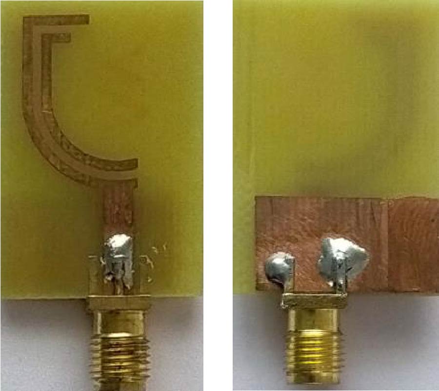
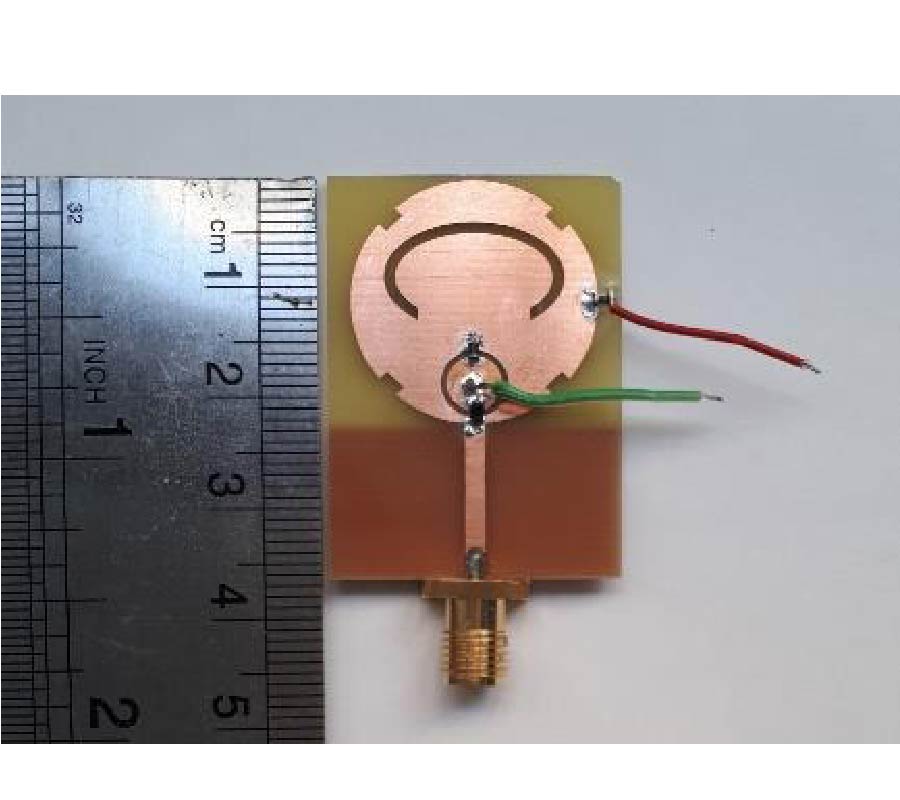
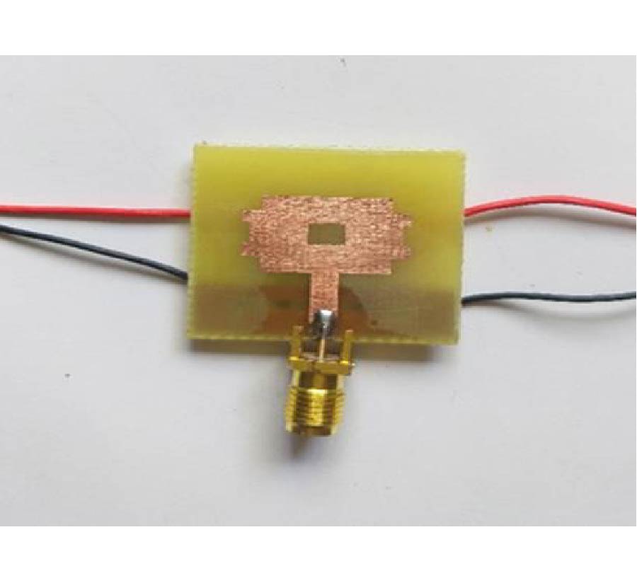
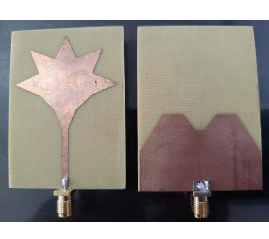
A compact (25×28×1.57 mm3) and wide-band multimode frequency tunable antenna with defected ground structure (FRDGS) for 4G and 5G conformal portable devices and multi-band wireless systems is presented in this article. In a previous study, frequency reconfigurable antenna designs only used the method of adding slots on the patch or ground. In this study, a combination of multiple slots, partial ground, and defective ground structure techniques were utilised to attain the advantages of compactness, wide impedance bandwidth, and steady radiation pattern. Multiple slots on the top layer of the substrate and F-shaped slot etched at the bottom makes the proposed antenna. Two PIN diodes are inserted in the F-shaped slot for frequency reconfiguration, allowing the antenna to switch between different resonances. Ansys high frequency structure simulator 15.0v is used to simulate the antenna parameters. This antenna performance is demonstrated using measured and simulated data. The simulated and measured results clearly show that the proposed antenna can switch between six dissimilar resonant frequency bands via various modes of operation across the frequency spectrum from 2.3 to 8.9 GHz. The antenna works in a variety of commercial bands, such as WLAN/Bluetooth (2.4-2.5 GHz), LTE/4G (2.3-2.7 GHz), S-band (2-4 GHz), Radio Navigation (2.7-2.9 GHz), and 5G/sub-6 (3.3-4.9 GHz), according to simulations and experiments. The proposed design features narrowband, wideband, and ultra-wideband properties with a consistent radiation pattern, adequate gain (1.6 to 5.8 dB), and high radiation efficiency (86 to 94%) in a small package. Furthermore, the performance comparison of the proposed antenna with that of the state-of-the-art antennas in terms of compactness, frequency reconfigurability, number of operating bands, and impedance bandwidth demonstrates the novelty of the proposed antenna and its potential application in multiple wireless applications.
WIDE-BAND FREQUENCY TUNABLE ANTENNA FOR 4G, 5G/SUB 6 GHZ PORTABLE DEVICES AND MIMO APPLICATIONS
2022-01-20
PIER C
Vol. 118, 11-24, 2022
download: 292
Defected Star-Shaped Microstrip Patch Antenna for Broadband Applications
Mahesh Shankar Pandey and Virendra Singh Chaudhary
This research article proposes a Defected Star-Shaped Microstrip Antenna (DSSMSA) for wideband applications. A designed monopole antenna has a defected star-shaped tuning stub with a defected ground structure energised with a microstrip feed line. An appropriate tuning of resonating modes wideband frequency effect has been achieved by optimising the dimensions of the tuning stub and the dimensions of the defected ground and its notch. Surface current distribution plays a vital role in optimising the antenna geometry and developing mathematical resonating frequencies equations. The simulated and experimental results show that the DSSMSA radiates under the frequency band from 1.6638 GHz to 6.652 GHz with measured fractional bandwidth of 119.9692% for |S11| < -10 dB. Optimised DSSMSA resonates at frequencies 2.05 GHz, 3.382 GHz, and 5.494 GHz. As the geometry of DSSMSA is symmetrical, the symmetric far-field pattern has been found in the far-field.
DEFECTED STAR-SHAPED MICROSTRIP PATCH ANTENNA FOR BROADBAND APPLICATIONS
2022-01-18
PIER C
Vol. 118, 1-10, 2022
download: 169
A Novel Surface Wave Diplexer Based on Tensor Impedance Surfaces
Mojtaba Mighani
In this paper, a new Surface Wave (SW) diplexer in frequency bands of 11.6 GHz and 19.3 GHz is presented based on the frequency variations of the refractive angle when an SW enters from a Scalar Impedance Sheet (SIS) to a Tensor Impedance Sheet (TIS). In this structure, a SIS has been placed alongside a TIS, and using three launchers, SW is excited and received on them. To achieve an SW diplexer, the structure is designed in a way that the refractive angle changes in the expected range when SW enters from SIS to TIS. Finally, the proposed structure is fabricated and measured by printed circuit technology. The measurement results at 11.6 GHz and 19.3 GHz show that this structure has 3.6 dB and 4.1 dB insertion losses and 33.5 dB and 37 dB isolations in the two bands, respectively. These measurements are in good agreement with mathematical modelling and simulations.
A NOVEL SURFACE WAVE DIPLEXER BASED ON TENSOR IMPEDANCE SURFACES