Vol. 48
Latest Volume
All Volumes
PIERC 148 [2024] PIERC 147 [2024] PIERC 146 [2024] PIERC 145 [2024] PIERC 144 [2024] PIERC 143 [2024] PIERC 142 [2024] PIERC 141 [2024] PIERC 140 [2024] PIERC 139 [2024] PIERC 138 [2023] PIERC 137 [2023] PIERC 136 [2023] PIERC 135 [2023] PIERC 134 [2023] PIERC 133 [2023] PIERC 132 [2023] PIERC 131 [2023] PIERC 130 [2023] PIERC 129 [2023] PIERC 128 [2023] PIERC 127 [2022] PIERC 126 [2022] PIERC 125 [2022] PIERC 124 [2022] PIERC 123 [2022] PIERC 122 [2022] PIERC 121 [2022] PIERC 120 [2022] PIERC 119 [2022] PIERC 118 [2022] PIERC 117 [2021] PIERC 116 [2021] PIERC 115 [2021] PIERC 114 [2021] PIERC 113 [2021] PIERC 112 [2021] PIERC 111 [2021] PIERC 110 [2021] PIERC 109 [2021] PIERC 108 [2021] PIERC 107 [2021] PIERC 106 [2020] PIERC 105 [2020] PIERC 104 [2020] PIERC 103 [2020] PIERC 102 [2020] PIERC 101 [2020] PIERC 100 [2020] PIERC 99 [2020] PIERC 98 [2020] PIERC 97 [2019] PIERC 96 [2019] PIERC 95 [2019] PIERC 94 [2019] PIERC 93 [2019] PIERC 92 [2019] PIERC 91 [2019] PIERC 90 [2019] PIERC 89 [2019] PIERC 88 [2018] PIERC 87 [2018] PIERC 86 [2018] PIERC 85 [2018] PIERC 84 [2018] PIERC 83 [2018] PIERC 82 [2018] PIERC 81 [2018] PIERC 80 [2018] PIERC 79 [2017] PIERC 78 [2017] PIERC 77 [2017] PIERC 76 [2017] PIERC 75 [2017] PIERC 74 [2017] PIERC 73 [2017] PIERC 72 [2017] PIERC 71 [2017] PIERC 70 [2016] PIERC 69 [2016] PIERC 68 [2016] PIERC 67 [2016] PIERC 66 [2016] PIERC 65 [2016] PIERC 64 [2016] PIERC 63 [2016] PIERC 62 [2016] PIERC 61 [2016] PIERC 60 [2015] PIERC 59 [2015] PIERC 58 [2015] PIERC 57 [2015] PIERC 56 [2015] PIERC 55 [2014] PIERC 54 [2014] PIERC 53 [2014] PIERC 52 [2014] PIERC 51 [2014] PIERC 50 [2014] PIERC 49 [2014] PIERC 48 [2014] PIERC 47 [2014] PIERC 46 [2014] PIERC 45 [2013] PIERC 44 [2013] PIERC 43 [2013] PIERC 42 [2013] PIERC 41 [2013] PIERC 40 [2013] PIERC 39 [2013] PIERC 38 [2013] PIERC 37 [2013] PIERC 36 [2013] PIERC 35 [2013] PIERC 34 [2013] PIERC 33 [2012] PIERC 32 [2012] PIERC 31 [2012] PIERC 30 [2012] PIERC 29 [2012] PIERC 28 [2012] PIERC 27 [2012] PIERC 26 [2012] PIERC 25 [2012] PIERC 24 [2011] PIERC 23 [2011] PIERC 22 [2011] PIERC 21 [2011] PIERC 20 [2011] PIERC 19 [2011] PIERC 18 [2011] PIERC 17 [2010] PIERC 16 [2010] PIERC 15 [2010] PIERC 14 [2010] PIERC 13 [2010] PIERC 12 [2010] PIERC 11 [2009] PIERC 10 [2009] PIERC 9 [2009] PIERC 8 [2009] PIERC 7 [2009] PIERC 6 [2009] PIERC 5 [2008] PIERC 4 [2008] PIERC 3 [2008] PIERC 2 [2008] PIERC 1 [2008]
2014-03-26
PIER C
Vol. 48, 167-175, 2014
download: 274
Design and Study of Uniplanar Coupled Inverted-L Antenna for Single-/Dual-Band Operation
Chao-Shun Yang and Christina F. Jou
A coupled-line-based planar antenna for single-band and dual-band operation is presented. The well-known uniplanar coupled inverted-L antenna (UCILA) has a simple and specific mechanism to achieve the dual-band ratio that was not described in the past. The UCILA which shunted a short stub in the slotline portion can provide switchable modes among single-low band (3.4% for WLAN 2.44 GHz), single-high band (15% for WLAN 5.2-5.8 GHz band) and dual-band (WLAN 2.44/5-6 GHz) operations.
DESIGN AND STUDY OF UNIPLANAR COUPLED INVERTED-L ANTENNA FOR SINGLE-/DUAL-BAND OPERATION
2014-03-24
PIER C
Vol. 48, 159-166, 2014
download: 560
Wideband Dual-Polarized Crossed-Dipole Antenna with Parasitical Crossed-Strip for Base Station Applications
Shaoli Zuo , Qiong-Qiong Liu and Zhi-Ya Zhang
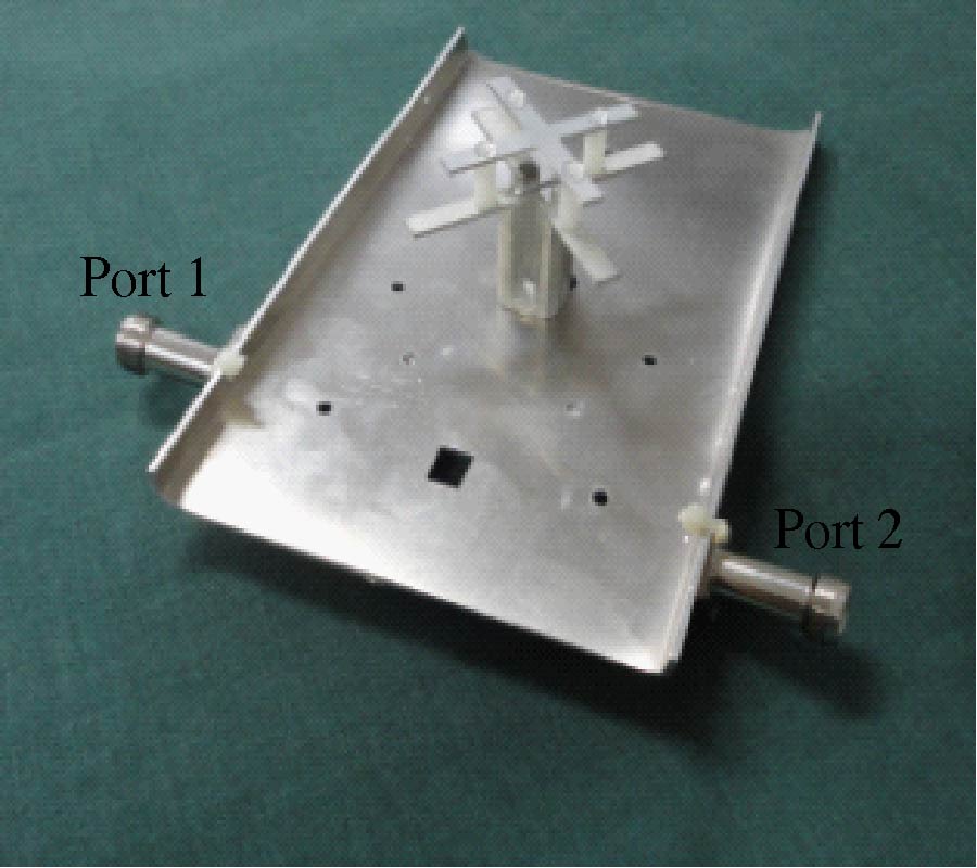
A wideband dual-polarized crossed-dipole antenna with parasitical crossed-strip for base-station applications is presented. By using a pair of orthogonal crossed-dipoles, two linear polarizations (+45°) are obtained. A parasitical crossed-strip is introduced to improve the impendence bandwidth and enhance the isolation (S12) between the two orthogonal polarizations of the upper band. The antenna shows a wideband impedance characteristic about 34.9% for S11≤-10 dB (+45° polarization) and S22≤-10 dB (-45° polarization). High isolation (S12≤-32 dB) between the two polarizations in the required band are obtained. The stable peak gain, unidirectional radiation patterns and low cross-polarization over the whole operating band are also achieved. Due to its good performance, simple fabrication technique and low cost, the antenna is very suitable for potential base station applications in mobile communication such as DCS, PCS and UMTS.
WIDEBAND DUAL-POLARIZED CROSSED-DIPOLE ANTENNA WITH PARASITICAL CROSSED-STRIP FOR BASE STATION APPLICATIONS
2014-03-24
PIER C
Vol. 48, 151-157, 2014
download: 242
Prediction Model of Shielding Effectiveness of Electromagnetic Shielding Fabric with Rectangular Hole
Zhe Liu , Yalan Yang , Xiuchen Wang and Zhong Zhou
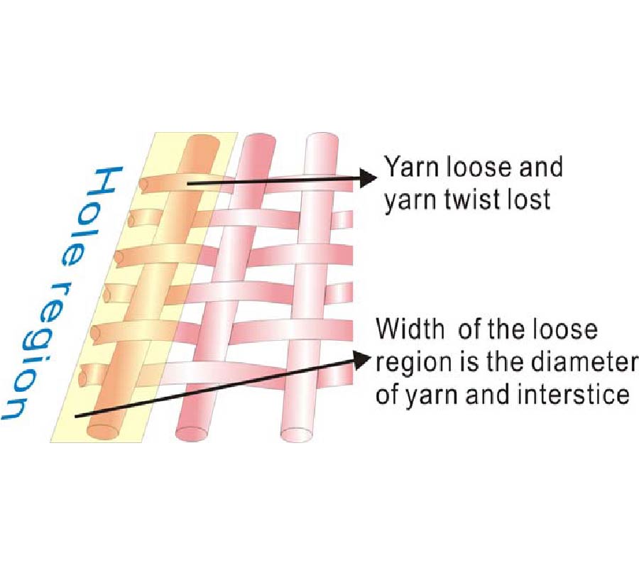
Electromagnetic shielding (EMS) fabrics often need to design rectangular holes for application. However, there is not a mature approach to predict the shielding effectiveness (SE) of the EMS fabric with rectangular hole. This paper proposes that there are a number of loose regions of conductive fibers on the hole edge of the EMS fabric, and establishes a SE prediction model of the EMS fabric with rectangular hole. Firstly, the loose region of conductive fiber is analyzed to build a model of the rectangular hole. Secondly, the SE prediction model of the EMS fabric with rectangular hole is deduced according to the transmission coefficient of the normal region, hole region and loose region, and the determining method of the loose region is given. Finally, the prediction model is verified by experiments. The results show that the model can successfully predict the SE of the EMS fabric with the plain, twill and satin weaves, and the factors such as frequency, fabric density and metal fiber content have little influence on the model. The proposed model can provide a valuable reference for the rational design of the rectangular hole of the EMS fabric.
PREDICTION MODEL OF SHIELDING EFFECTIVENESS OF ELECTROMAGNETIC SHIELDING FABRIC WITH RECTANGULAR HOLE
2014-03-21
PIER C
Vol. 48, 141-150, 2014
download: 432
Design of h -Plane Inductance Diaphragm Waveguide Band-Pass Filter for Millimeter Imaging Frontend
Baohua Yang , Zhi-Ping Li , Jin Zhang , Xianxun Yao , Cheng Zheng , Xiaozhou Shang and Jungang Miao
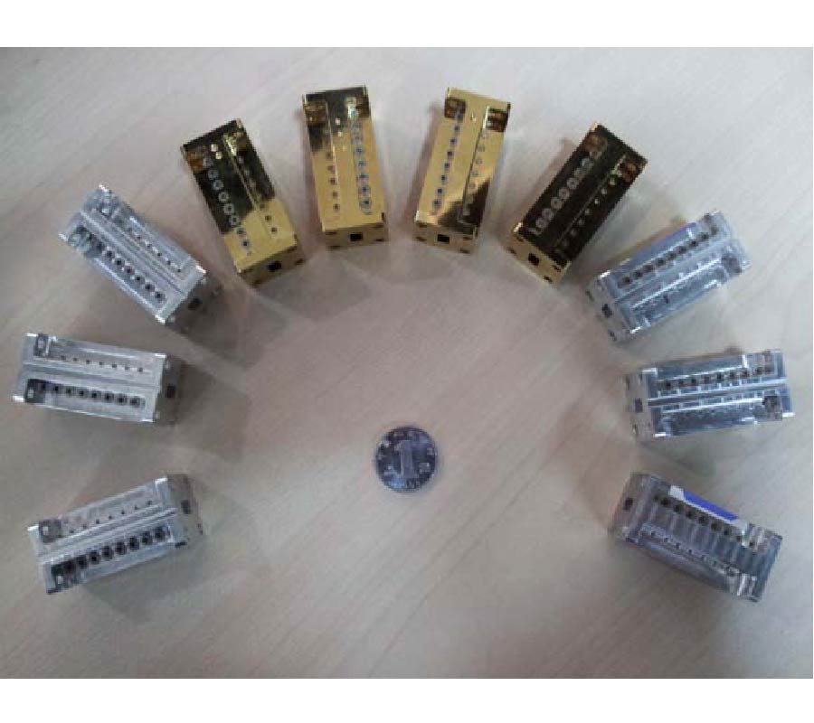
This study presents an equivalent circuit and a design of an H-plane waveguide bandpass filter (BPF) with chamfer. Traditionally, only thin inductive diaphragm with no chamfers considered in the direct-coupled cavity theory, but this will lead to difficulties in the BPF manufacturing. During manufacturing process the chamfer cannot be avoided, and its equivalent circuit and effects on frequency shifting are investigated in this paper. A new design method is proposed in order to compensate the effect of chamfer in the half-wavelength resonator connection between the inductance diaphragm and the waveguide. A modified empirical formula and corresponding procedure are provided for designing such filters. The working center frequency and 3 dB bandwidths (BW) are simulated considering different chamfer radius. The simulated center frequencies are 18 GHz, 26 GHz, 34 GHz and 42 GHz, and BWs are 2.265%, 2.5%, 10%, 15% and 20%. Results show that the modified formula, which conforms better with the simulated results, is superior to the traditional formula. Two H-plane waveguide BPFs are manufactured with center frequency 26 GHz with 2.5% BW and 34 GHz with 2.265% BW. The results of the modified formula are in good agreement with measured ones.
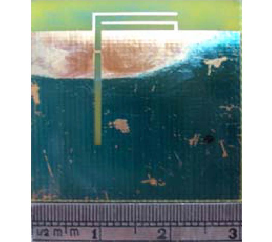
DESIGN OF H-PLANE INDUCTANCE DIAPHRAGM WAVEGUIDE BAND-PASS FILTER FOR MILLIMETER IMAGING FRONTEND
2014-03-20
PIER C
Vol. 48, 133-139, 2014
download: 208
An Efficient Fixed Rate Transmission Scheme Over Delay-Constrained Wireless Fading Channels
Xiangyu Gao and Yuesheng Zhu
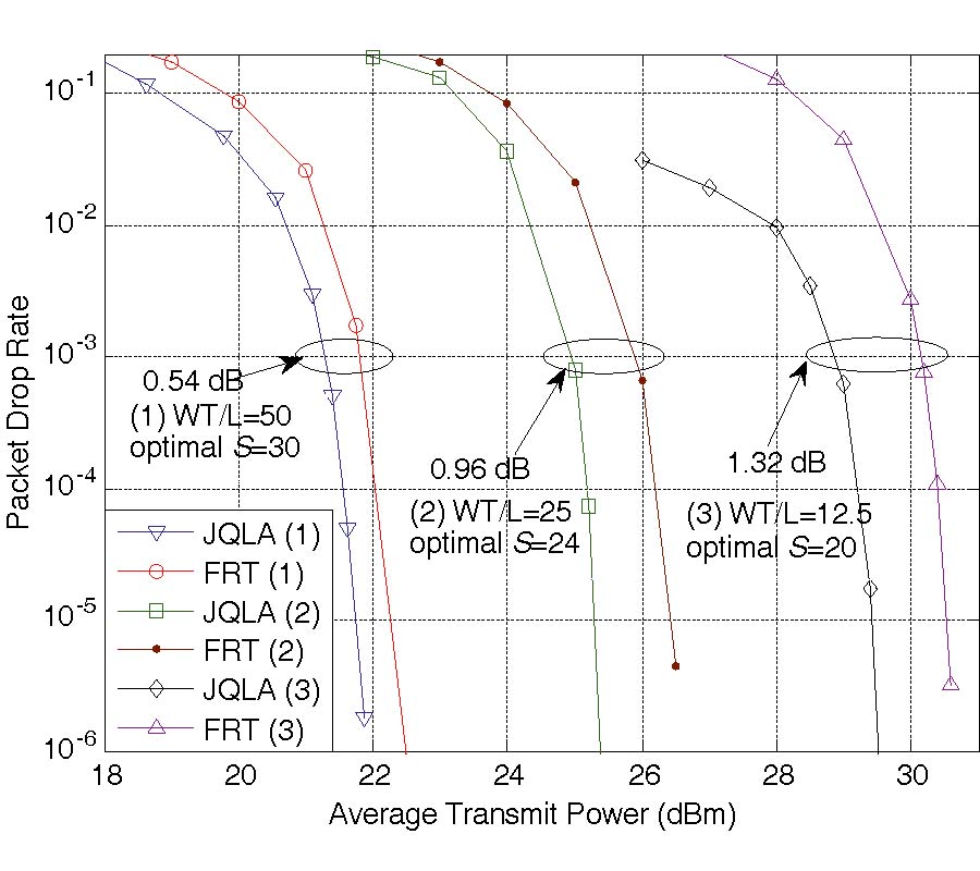
In this paper, we study the scheduler design problems over delay-constrained wireless communication links. Following a crosslayer design approach, the wireless system is modeled as a joint link-PHY layer architecture with a finite-length buffer and continuousstate fading links. A heuristic and efficient fixed rate transmission scheduler scheme (FRT) is proposed. We formulate and analyze the performance of the FRT scheme in terms of power efficiency and packet drop rate. Compared with variable rate schemes, the FRT scheme can considerably simplify the hardware implementation of transmitter. In addition, we show that the optimization of FRT scheme can be conducted with significantly reduced computational cost by utilizing the sparse feature of the transition probability matrix. Moreover, the simulation results show that at the packet drop rate of 10-3, the optimized average transmit power of FRT scheme is only 0.5 dB higher than the known optimal variable rate scheme, indicating that the FRT scheme is quite power efficient as well. Therefore, we conclude that the FRT scheme is more feasible than variable rate schemes in practical delayconstrained wireless systems with regard to both hardware cost and power efficiency.
AN EFFICIENT FIXED RATE TRANSMISSION SCHEME OVER DELAY-CONSTRAINED WIRELESS FADING CHANNELS
2014-03-18
PIER C
Vol. 48, 125-132, 2014
download: 558
Doppler Spread Spectrum of a Circularly Moving Receiver in an Anechoic and a Reverberation Chamber
Myunghun Jeong , Byoung-Yong Park , Junghwan Choi and Seong-Ook Park
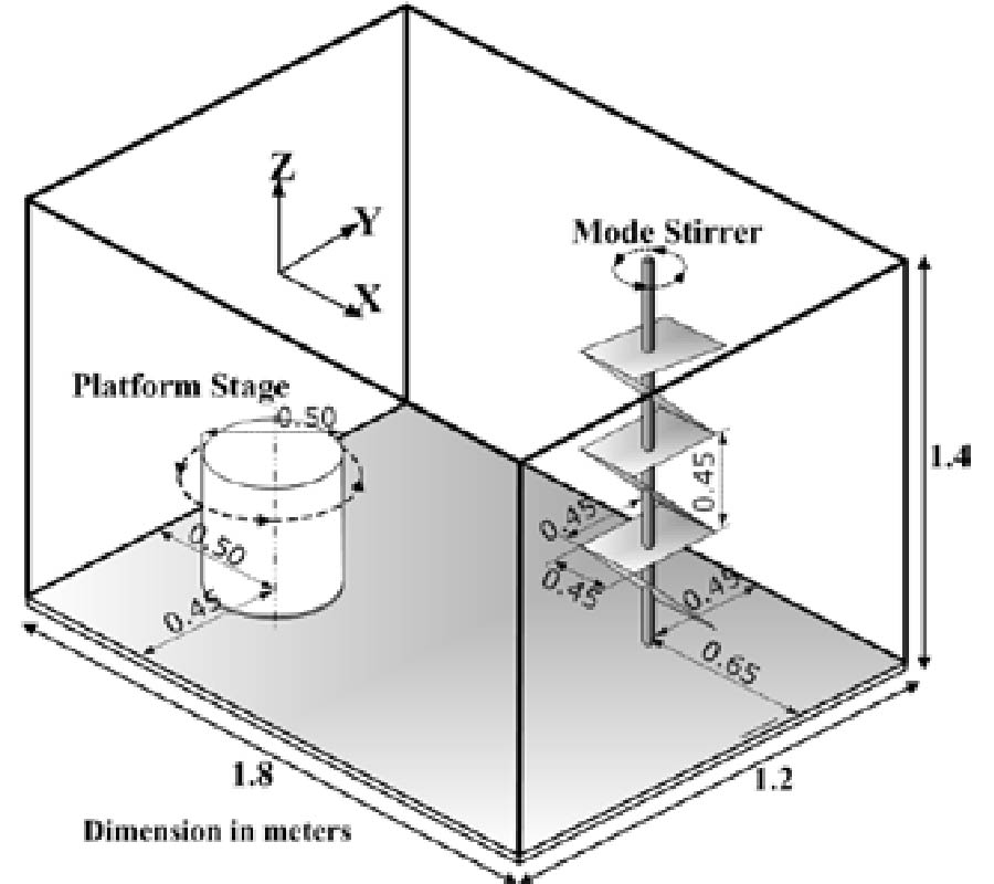
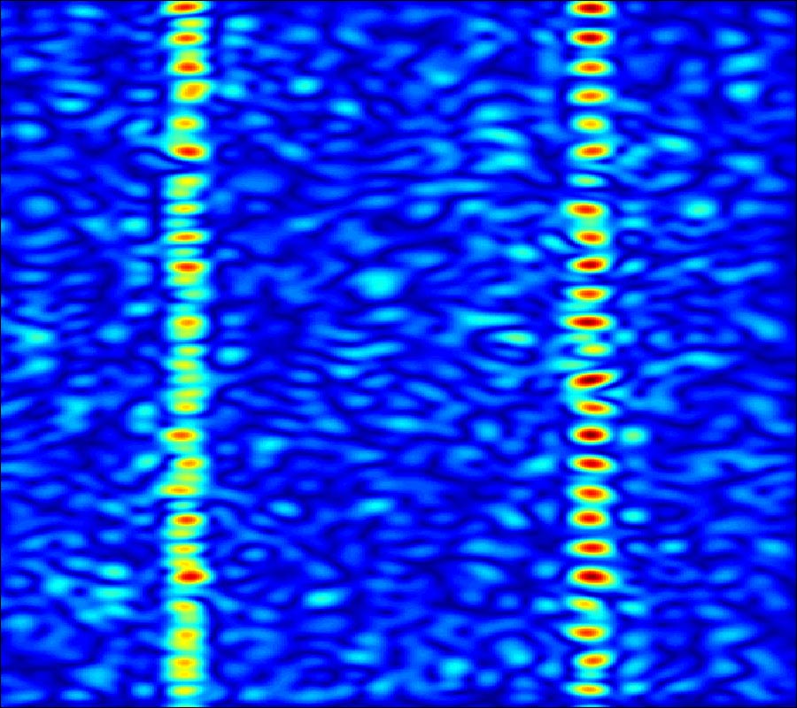
The Doppler phenomena caused by a moving receiver or environmental scatters around a receiver are emulated in an AC(Anechoic Chamber) and a RC(Reverberation Chamber) using platform and mode stirring. In order to verify the emulated Doppler spread spectrum, the measured results in the AC and the RC have been investigated to incorporate Jakes's and 802.11 TGn Doppler models, respectively.
DOPPLER SPREAD SPECTRUM OF A CIRCULARLY MOVING RECEIVER IN AN ANECHOIC AND A REVERBERATION CHAMBER
2014-03-18
PIER C
Vol. 48, 111-123, 2014
download: 257
A Novel Planar Structure for Implementing Power Divider OR Balun with Variable Power Division
Weiwei Zhang , Yuan'an Liu , Yongle Wu , Junyu Shen , Shulan Li , Cuiping Yu and Jinchun Gao
A simple and analytical design methodology for a novel planar four-port structure to implement power divider (PD) or balun with variable power division is proposed in this paper. It consists of two different 3 dB branch-line couplers and one coupled-line phase shifter whose length can be changed to implement variable power division. Different from the previous designs, the power divider and balun with variable power division can be realized in only one circuit by changing the electrical length θ0 of the coupled line when the impedance ratio g is selected. According to the ABCD parameters and linear algebra calculation, closed-form mathematical equations for the circuit electrical values and scattering parameters can be obtained. A prototype with this proposed circuit, operating at 2 GHz, has been designed and fabricated using microstrip technology. Good agreements between the calculated and measured results verify our design.
A NOVEL PLANAR STRUCTURE FOR IMPLEMENTING POWER DIVIDER OR BALUN WITH VARIABLE POWER DIVISION
2014-03-15
PIER C
Vol. 48, 103-110, 2014
download: 242
DRA Reflectarray Unit Elements with Thin Under-Loading Parallel Slots
Shin-Rou Lee , Eng Hock Lim and Fook-Loong Lo
This paper presents three dielectric resonator (DR) unit elements loaded with one, two, and three narrow slots underneath for designing reflectarrays. The slots are aligned in parallel, and the lengths are varied to function as phase shifter for changing reflection phase. It is found that the dominant TE mode of the square DR element can be easily excited by placing multiple parallel slots beneath a DR element. Study shows that the number and width of the slots can be used as additional design parameters for tuning the reflection loss and phase range of the reflectarray. Rectangular waveguide method has been deployed, showing reasonable agreement between simulation and measurement. It is found that a reasonable reflection phase range of 313° with slow slope is obtainable when the DRA is loaded with two slots beneath, which can be used for designing a small-size reflectarray. The reflection characteristics of the unit elements are studied, along with a complete parametric analysis.
DRA REFLECTARRAY UNIT ELEMENTS WITH THIN UNDER-LOADING PARALLEL SLOTS
2014-03-14
PIER C
Vol. 48, 95-102, 2014
download: 386
Novel Jamming Suppression Method Using Polarization SAR Data
Xiao-Hong Lin , Guo-Yi Xue and Peiguo Liu
Barrage and deceptive jamming can mask the synthetic aperture radar (SAR) signals and render SAR useless. In this paper, a novel jamming suppression method based on plolarization SAR (PolSAR) is proposed. After range compression, the barrage jamming has a noise-like characteristic while the real echo and deceptive jamming are focused. According to this, the barrage jamming is removed via a minimum entropy algorithm. Based on the different polarization characteristics between deceptive jamming and the real echo, the deceptive jamming can be suppressed by phase compensation in doppler domain. Simulation results are shown to demonstrate the validity of the proposed method.
NOVEL JAMMING SUPPRESSION METHOD USING POLARIZATION SAR DATA
2014-03-13
PIER C
Vol. 48, 87-93, 2014
download: 273
Design of Dual Band Notch UWB Monopole Antenna Using Dual-Arm Spiral Resonator
Pradeep Kumar , Zachariah Callottu Alex and Krishnan Shambavi
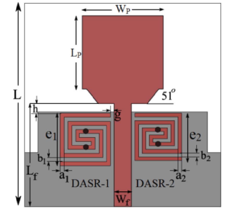
An ultra wideband (UWB) monopole antenna with dual band-notch characteristic is proposed. Dual arm spiral resonators (DASR) are placed on both sides of the feed line to create band notches at 5.25 and 5.8 GHz for the upper and lower WLAN bands respectively. First the antenna is optimized individually for both upper and lower WLAN band-notch behaviors then embedded together for dual band-notch characteristic. The measured results ensure that two band notches are achieved, and the antenna can be used for UWB applications without any interference from WLAN band.
DESIGN OF DUAL BAND NOTCH UWB MONOPOLE ANTENNA USING DUAL-ARM SPIRAL RESONATOR
2014-03-12
PIER C
Vol. 48, 77-86, 2014
download: 268
A Modified Synchronization Method for Bistatic SAR
Yunfeng Shao , Yue Liu , Runpu Chen and Gang Liu
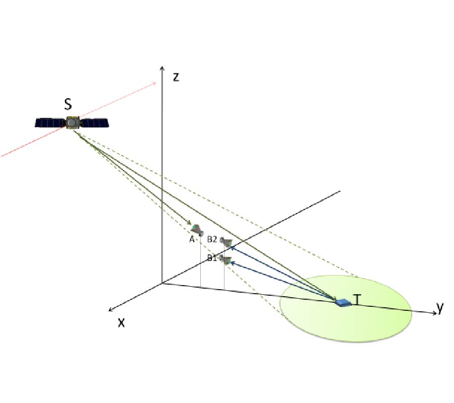
It is a common synchronization approach of the bistatic Synthetic Aperture Radar (BiSAR) with spaceborne/stationary configuration that obtains synchronization information from a direct signal. An easy and effective synchronization method is using the direct signal as a match filter to compress the echo for range compression. This method requires a high signal-to-noise ratio (SNR) of the direct signal, because the low SNR of the direct signal affects the synchronization result. Furthermore, it affects the imaging quality and bistatic-InSAR (BiInSAR) result seriously. Two factors affect the SNR of the direct signal: low gain and saturation. The transmitter and receiver antenna beam patterns cause the received direct signal's power variance during the exposure time. The requirement of high gain and no saturation cannot be satisfied simultaneously during the exposure time when the receiver sub-system does not have automatic gain control (AGC). In this paper, a modified synchronization approach is proposed. The proposed method not only tolerates the low gain and saturation, but also does not require the parameters of the transmitted signal, such as FM chirp rate, bandwidth and transmitted pulse length. The proposed method makes the gain design of the synchronization channel easy. The experiment results verifies the effectiveness of the proposed approach.
A MODIFIED SYNCHRONIZATION METHOD FOR BISTATIC SAR
2014-03-11
PIER C
Vol. 48, 69-76, 2014
download: 246
Design of a Novel Antenna and Its Characterization in Frequency and Time Domains for Ultra Wide Band Applications.
Mohamed Ershadh , Phani Krishna , Bhayaveni and Savithri Subramanian
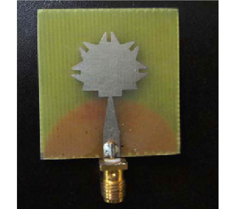
A novel compact planar monopole antenna for UWB applications is proposed in this paper. The proposed novelty of the antenna is attributed to the addition of suitable beveled stubs to a basic circular geometry of the radiator as an improved impedance matching technique to achieve enhanced radiation performances. The feed circuit is a tapered microstrip line with a matching section over a semi-elliptical ground plane. The proposed antenna achieves sufficient impedance bandwidth for a VSWR<2 for frequencies from 3-15 GHz covering the entire UWB range (3.1-10.6 GHz), which is verified experimentally. Also this design achieves good gain, constant group delay and a near omni-directional radiation pattern over the UWB band. The UWB characteristics of the antenna are evaluated in frequency and time domains. Results reveal that the proposed antenna has flat transfer function, linear phase and good impulse response with virtually no ringing which are the essential requirements for an UWB antenna for efficient pulse transmission/reception. The simulated and measured results of these parameters are presented. The performance results of the novel antenna with other designs is also compared and presented.
DESIGN OF A NOVEL ANTENNA AND ITS CHARACTERIZATION IN FREQUENCY AND TIME DOMAINS FOR ULTRA WIDE BAND APPLICATIONS.
2014-03-10
PIER C
Vol. 48, 61-68, 2014
download: 312
Mutual Coupling Reduction of a Dual-Frequency Microstrip Antenna Array by Using U-Shaped DGS and Inverted U-Shaped Microstrip Resonator
Chandan Kumar Ghosh , Bappaditya Mandal and Susanta Kumar Parui
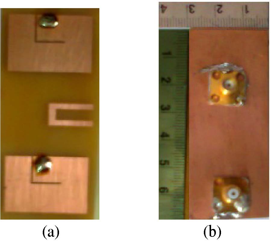
A compact U-shaped defective ground structure (DGS) and an inverted U-shaped resonator are introduced in order to reduce the mutual coupling (MC) between two slotted microstrip antennas at two different resonance frequencies. The proposed DGS and resonator have the same electrical length and both are placed in between two patch antennas, as a technique to suppress the occurrence of MC at two different frequency bands. The DGS and the resonator offer stop bands at 2.45 GHz and 4.5 GHz respectively. Simulated results show a reduction in MC of 20 dB at 2.45 GHz band and 10 dB at 4.5 GHz band. We have developed experimental models that have proved this concept of MC reduction. Finally, the influence of other parameters of the proposed antenna at the presence of the combination of DGS and resonator in the array system has been studied. Prototype antennas for different combinations of DGS and resonator and two-element array integrated with DGS and resonator have been fabricated, measured and the idea has been verified. A good agreement is observed between measured and the simulated results.
MUTUAL COUPLING REDUCTION OF A DUAL-FREQUENCY MICROSTRIP ANTENNA ARRAY BY USING U-SHAPED DGS AND INVERTED U-SHAPED MICROSTRIP RESONATOR
2014-03-07
PIER C
Vol. 48, 53-60, 2014
download: 294
An Improvement to Directional Equiangular Spiral Antenna with Wide CP Band, High Gain and Low Profile
Xiang Liu , Jun-Ping Geng , Xianling Liang , Rong-Hong Jin , Cheng Zhang and Kun Wang
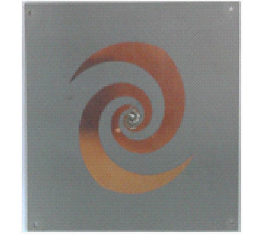
An improved directional equiangular spiral antenna with wide CP band and high gain is proposed, in which the impedance bandwidth is 2~12 GHz, CP bandwidth 4.5~7 GHz, and gain 6~9.5 dBi. The antenna includes 4 layers. The top layer is equiangular spiral antenna, and the bottom layer is ground. The middle two layers are parasitic metal films with irregular rectangular holes, which are introduced to improve the performance of equiangular spiral antenna and reduce the profile. The measured results are in good agreement with the simulated ones.
AN IMPROVEMENT TO DIRECTIONAL EQUIANGULAR SPIRAL ANTENNA WITH WIDE CP BAND, HIGH GAIN AND LOW PROFILE
2014-03-05
PIER C
Vol. 48, 45-52, 2014
download: 338
Modified Bowtie Antenna for Zeroth Order Resonance
Thazhe Koralath Roshna , Unnimadhavan Deepak , Vallathadam Sajitha , Kesavath Vasudevan and Pezholil Mohanan
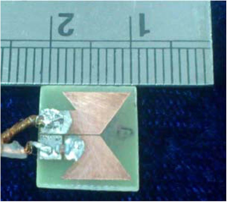
A novel extremely compact Zeroth Order Resonator (ZOR) antenna with a chip inductor, for Digital Video Broadcasting-Handheld (DVB-H) application, is presented. The proposed antenna has a bowtie structure with an overall dimension of 0.0186λ0 × 0.020λ0 × 0.003λ0 mm3 at 503 MHz. The zeroth resonance property makes the resonant frequency to be independent of the antenna dimension. The 3:1 VSWR bandwidth of the antenna is 39 MHz and offers an omnidirectional radiation pattern. A 99.1% reduction in the overall area of the structure is achieved compared to a conventional circular patch antenna operating at the same frequency.
MODIFIED BOWTIE ANTENNA FOR ZEROTH ORDER RESONANCE
2014-03-04
PIER C
Vol. 48, 37-44, 2014
download: 316
Planar Bandpass Filter with 100-dB Suppression Up to Tenfold Passband Frequency
Boris Afanasievich Belyaev , Alexey Mikhailovich Serzhantov , Vladimir V. Tyurnev , Yaroslav F. Bal'va and Aleksandr Leksikov
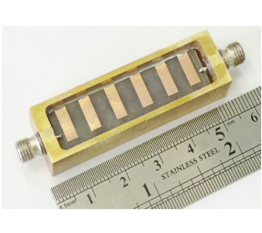
This paper proposes a miniature microwave bandpass filter. It comprises quasi-lumped suspended substrate stripline resonators of a new type. Their common substrate consists of two contiguous dielectric layers. Every resonator in the filter has three parallel strip conductors. Two of them are placed on the outer substrate surfaces and the rest is placed inside the substrate. The filter of the sixth order was designed with the use of special optimization rules that are universal for all resonator filters. The substrate of the fabricated filter was made of RT/Duroid 5880 (εr = 2.2, tan δ =0.002) with thickness of 0.127 mm. It has dimensions of 12 mm x 45.5 mm. The measured passband has a center frequency of 1.01 GHz, 3-dB fractional bandwidth of 11%, and minimum insertion loss of 1.4 dB. The 100-dB upper stopband extends up to 10.5 GHz.
PLANAR BANDPASS FILTER WITH 100-DB SUPPRESSION UP TO TENFOLD PASSBAND FREQUENCY
2014-03-04
PIER C
Vol. 48, 29-35, 2014
download: 272
Design of a Compact Triple-Band Monopole Planar Antenna for WLAN/WiMAX Applications
Shan Shan Huang , Jun Li and Jian Zhong Zhao
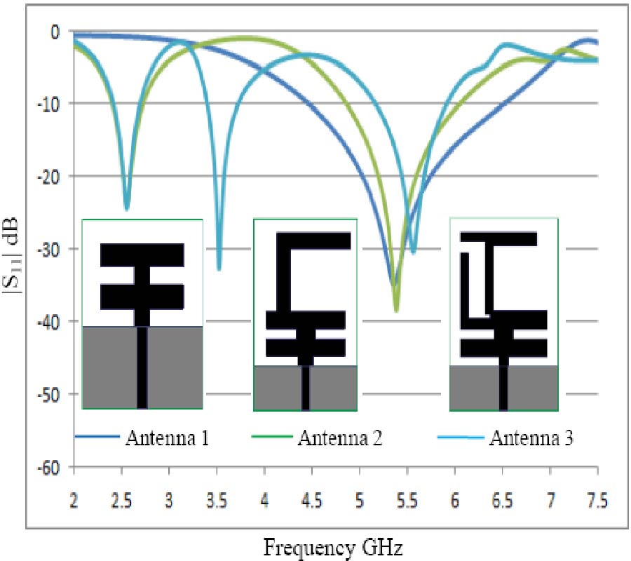
In this paper, a novel compact tri-band monopole antenna for WLAN/WiMAX applications is proposed. By using a horizontal H-shaped strip and an L-shaped open end stub, and a deformation inverted T-shaped strip through a matching line attached to the 50-Ω feed-line, tri-band has impedance bandwidths for S11≤ -10 dB are 2.4-2.7 GHz, 3.4-3.72 GHz, 5.06-5.85 GHz, covering 2.4/5.2/5/5.8 GHz for WLAN and 2.5/3.5/5.5 for WiMAX applications can be acquired. Experimental results show that the proposed tri-band antenna has nearly omnidirectional radiation characteristics across all the operation bands. Furthermore, the antenna with compact size of 30 × 20 × 0.8 mm3 has simple structures.
DESIGN OF A COMPACT TRIPLE-BAND MONOPOLE PLANAR ANTENNA FOR WLAN/WiMAX APPLICATIONS
2014-03-01
PIER C
Vol. 48, 21-28, 2014
download: 252
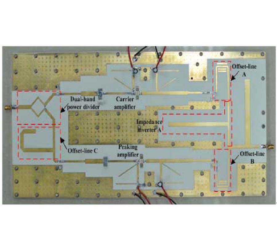
Design of a Dual-Band Doherty Power Amplifier Utilizing Simplified Phase Offset-Lines
Xuan Zheng , Yuan'an Liu , Cuiping Yu , Shulan Li and Jiuchao Li
This paper proposes a novel design methodology for dual-band Doherty power amplifier (DPA) with simplified offset-lines. The methodology is validated with the design and fabrication of a 10 W GaN based DPA for Global System for Mobile Communications (GSM) and Wideband Code Division Multiple Access (WCDMA) applications at 0.90 GHz and 2.14 GHz, respectively. In the measurement results, the DPA achieves a drain efficiency (DE) of 51.2% with an output power of 37.2 dBm at the 6.5 dB output power back-off (OBO) from the saturated output power at 0.90 GHz, and a DE of 39.9% with an output power of 37.4 dBm at the 6.5 dB OBO at 2.14 GHz. Linearity results using 20 MHz 16QAM signal show an adjacent channel leakage ratio (ACLR) of -48 dBc and -43 dBc with the average output power of 37.2 dBm and 37 dBm at 0.90 GHz and 2.14 GHz, respectively.
DESIGN OF A DUAL-BAND DOHERTY POWER AMPLIFIER UTILIZING SIMPLIFIED PHASE OFFSET-LINES
2014-02-26
PIER C
Vol. 48, 11-19, 2014
download: 394
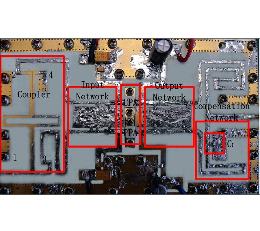
A Tradeoff Design of Broadband Power Amplifier in Doherty Configuration Utilizing a Novel Coupled-Line Coupler
Duye Ye , Yongle Wu and Yuan'an Liu
A broadband power amplifier designed and implemented in Doherty configuration is illustrated in this paper. Both input and output networks adopt the broadband matching topology. Additionally a compensation network, consisting of a series transmission line shunted with a capacitance, is set behind the peak amplifier to avoid in-band power leakage in the low-power section while at the cost of peak output power in partial band. A novel coupler is designed as an uneven power-divided splitter and experimentally validated for a broadband power amplifier module. A tradeoff of bandwidth, efficiency and output power is fulfilled through parameters select and postproduction tuning. According to the measured results, the proposed broadband Doherty power amplifier achieves an average saturated output power of 42 dBm, an average gain of 10.6 dB, an average peak and 6 dB back-off efficiency of 48.4% and 32.8%, respectively, and a fractional bandwidth of 51.4%, from 1.3 GHz to 2.2 GHz. The adjacent channel power ratio is better than -40 dBc when the amplifier is driven with 10-MHz QPSK signal, thus exhibiting a high linearity performance.
A TRADEOFF DESIGN OF BROADBAND POWER AMPLIFIER IN DOHERTY CONFIGURATION UTILIZING A NOVEL COUPLED-LINE COUPLER
2014-02-25
PIER C
Vol. 48, 1-9, 2014
download: 249
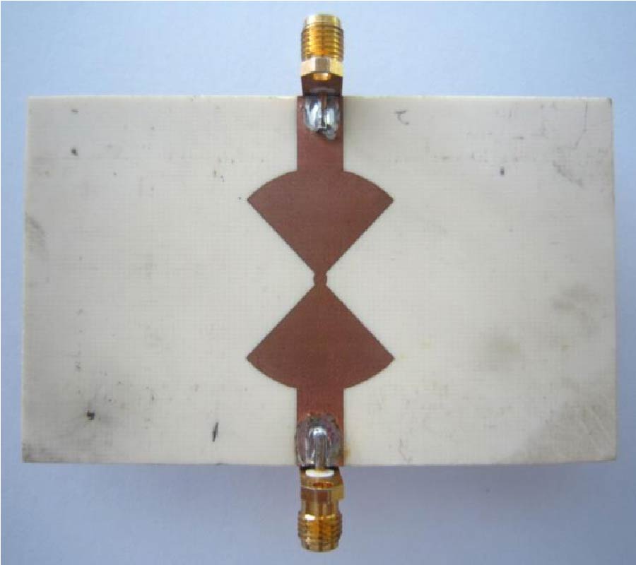
Broadside-Coupled Filtering Circular Patch Power Dividers
Y-Chun Khor Khor , Eng Hock Lim and Boon-Kuan Chung
Broadside coupling mechanism between different patch resonators is deployed for designing power dividers to provide bandpassing effect. To demonstrate, two sector-shaped patches are combined and concentrically stacked on top of a circular microstrip resonator where pairs of concentric arc-shaped slots and radial notches are etched to perturb the current distribution so that an additional pole can be obtained to broaden the operational bandwidth. The use of circular patch enables the expansion of output ports without increasing the design complexity. Also, it was found that broadside coupling generates transmission zeros which can be used to sharpen the rolloff skirt for a better selectivity. In this paper, the corresponding design theory and methodology are elucidated, together with the detailed parametric analysis.
BROADSIDE-COUPLED FILTERING CIRCULAR PATCH POWER DIVIDERS