Vol. 110
Latest Volume
All Volumes
PIERC 143 [2024] PIERC 142 [2024] PIERC 141 [2024] PIERC 140 [2024] PIERC 139 [2024] PIERC 138 [2023] PIERC 137 [2023] PIERC 136 [2023] PIERC 135 [2023] PIERC 134 [2023] PIERC 133 [2023] PIERC 132 [2023] PIERC 131 [2023] PIERC 130 [2023] PIERC 129 [2023] PIERC 128 [2023] PIERC 127 [2022] PIERC 126 [2022] PIERC 125 [2022] PIERC 124 [2022] PIERC 123 [2022] PIERC 122 [2022] PIERC 121 [2022] PIERC 120 [2022] PIERC 119 [2022] PIERC 118 [2022] PIERC 117 [2021] PIERC 116 [2021] PIERC 115 [2021] PIERC 114 [2021] PIERC 113 [2021] PIERC 112 [2021] PIERC 111 [2021] PIERC 110 [2021] PIERC 109 [2021] PIERC 108 [2021] PIERC 107 [2021] PIERC 106 [2020] PIERC 105 [2020] PIERC 104 [2020] PIERC 103 [2020] PIERC 102 [2020] PIERC 101 [2020] PIERC 100 [2020] PIERC 99 [2020] PIERC 98 [2020] PIERC 97 [2019] PIERC 96 [2019] PIERC 95 [2019] PIERC 94 [2019] PIERC 93 [2019] PIERC 92 [2019] PIERC 91 [2019] PIERC 90 [2019] PIERC 89 [2019] PIERC 88 [2018] PIERC 87 [2018] PIERC 86 [2018] PIERC 85 [2018] PIERC 84 [2018] PIERC 83 [2018] PIERC 82 [2018] PIERC 81 [2018] PIERC 80 [2018] PIERC 79 [2017] PIERC 78 [2017] PIERC 77 [2017] PIERC 76 [2017] PIERC 75 [2017] PIERC 74 [2017] PIERC 73 [2017] PIERC 72 [2017] PIERC 71 [2017] PIERC 70 [2016] PIERC 69 [2016] PIERC 68 [2016] PIERC 67 [2016] PIERC 66 [2016] PIERC 65 [2016] PIERC 64 [2016] PIERC 63 [2016] PIERC 62 [2016] PIERC 61 [2016] PIERC 60 [2015] PIERC 59 [2015] PIERC 58 [2015] PIERC 57 [2015] PIERC 56 [2015] PIERC 55 [2014] PIERC 54 [2014] PIERC 53 [2014] PIERC 52 [2014] PIERC 51 [2014] PIERC 50 [2014] PIERC 49 [2014] PIERC 48 [2014] PIERC 47 [2014] PIERC 46 [2014] PIERC 45 [2013] PIERC 44 [2013] PIERC 43 [2013] PIERC 42 [2013] PIERC 41 [2013] PIERC 40 [2013] PIERC 39 [2013] PIERC 38 [2013] PIERC 37 [2013] PIERC 36 [2013] PIERC 35 [2013] PIERC 34 [2013] PIERC 33 [2012] PIERC 32 [2012] PIERC 31 [2012] PIERC 30 [2012] PIERC 29 [2012] PIERC 28 [2012] PIERC 27 [2012] PIERC 26 [2012] PIERC 25 [2012] PIERC 24 [2011] PIERC 23 [2011] PIERC 22 [2011] PIERC 21 [2011] PIERC 20 [2011] PIERC 19 [2011] PIERC 18 [2011] PIERC 17 [2010] PIERC 16 [2010] PIERC 15 [2010] PIERC 14 [2010] PIERC 13 [2010] PIERC 12 [2010] PIERC 11 [2009] PIERC 10 [2009] PIERC 9 [2009] PIERC 8 [2009] PIERC 7 [2009] PIERC 6 [2009] PIERC 5 [2008] PIERC 4 [2008] PIERC 3 [2008] PIERC 2 [2008] PIERC 1 [2008]
2021-03-12
PIER C
Vol. 110, 267-283, 2021
download: 572
The Performance of Circularly Polarized Phased Sub-Array Antennas for 5G Laptop Devices Investigating the Radiation Effects
Korany Mahmoud , Abdullah Baz , Wajdi Alhakami , Hosam Alhakami and Ahmed Mohamed Montaser
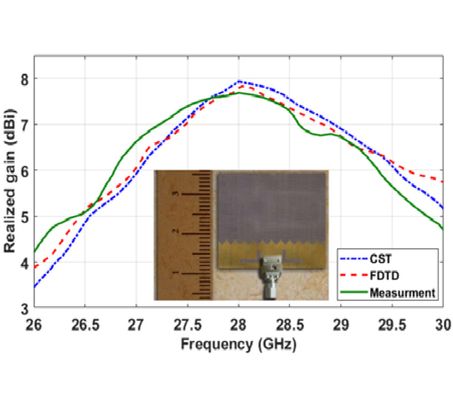
In this paper, the performance of circularly polarized (CP) adaptive sub-arrays integrated into 5G laptop device is investigated in the presence of a whole-body human phantom model. In addition, the radiation effect of the steered beam patterns has been analyzed by calculating the specific absorption rate distribution and temperature rise. In this target, a single-feed CP antenna element has been firstly designed to resonate at 28 GHz with high realized gain and radiation efficiency. Then, 4 sub-arrays have been constructed in a rectangular configuration with four-elements for each sub-array. To let the study more realistic, a complete human model is considered to investigate the radiation effects. The measured reflection coefficient and realized gain results of the designed antenna element are found to be -30 dB and 7.82 dB, respectively, in the assigned frequency band. Likewise, the antennas sub-arrays have approximately kept the same impedance matching attitude with high insertion loss of -22 dB and a realized gain and radiation efficiency of 16.85 dB and 86%, respectively, on average. Furthermore, the sub-arrays scan patterns and coverage efficiency has been studied considering the existence of the human body in different scenarios. Regarding the RF exposure, the results show that the resultant maximum values of specific absorption rate and power density do not exceed 1.52 W/Kg and 3.5 W/m2, respectively, whereas, the maximum exposure temperature in such a case is less than 2.8°C after 30 minutes and decreases to 0.5°C after a penetration depth of 3 mm which reflects the possibility of safe use.
THE PERFORMANCE OF CIRCULARLY POLARIZED PHASED SUB-ARRAY ANTENNAS FOR 5G LAPTOP DEVICES INVESTIGATING THE RADIATION EFFECTS
2021-03-10
PIER C
Vol. 110, 253-265, 2021
download: 379
A New Fast, Memory Efficient Wireless Electromagnetic Beamformer Antenna with Fast Tracking for 5/6G Systems
Herman Kunsei , Kandasamy Pirapaharan and Paul R. P. Hoole
The much-anticipated year of 5G deployment has lapsed, and yet much research is ongoing on the 5G New Radio (NR) interface. The quality of service and user experience is dependent on a stable and signal strength of the wireless communication link. To serve multiple users per sector accessing dedicated and unique services pose a challenge for passive antenna systems with omnidirectional beams. Smart 5G antenna technology with null forming and beamforming promises to serve mobile users well by offering a reliable wireless communication link. To address this need, we propose a 2 x 2 MIMO antenna capable of electronically forming electromagnetic beams in one direction and nullifying electromagnetic beams in any undesired direction. We demonstrate the usefulness of the proposed antenna by evaluating five cases that showed interesting insights, confirming the hypothesis that it is possible to implement beamforming in a 2 x 2 MIMO system with less computing power and minimum number crunching. What is novel and attractive about the proposed antenna are: (a) forming a beam with maximum directivity towards the desired user, while (b) simultaneously producing nulls towards an undesirable transmitter, and (c) a fast electromagnetic tracking module inbuilt into it so that the base station antenna may constantly track and maintain the communication link with the moving wireless transceiver or cell phone. While most wireless mobile systems use two separate software modules for beamforming and tracking the mobile station, the method presented here does electronic beamforming and tracking of the mobile user with a single low memory, computationally fast technique within the range of 10 ms to 19 s.
2021-03-09
PIER C
Vol. 110, 243-252, 2021
download: 300
Compact Self-Quadruplexing Antenna Based on SIW Cavity-Backed with Enhanced Isolation
Abhay Kumar Singh and Paras
A self-quadruplexing antenna based on substrate integrated waveguide (SIW) is presented. A slot is engraved on its top surface of the SIW cavity, which generates four different resonant frequencies (around 6.54, 7.64, 8.30, and 9.60 GHz) when it is excited by four 50 Ω microstrip feed lines. Also, each resonant frequency can be controlled independently. Due to a quarter mode (QM) cavity, the antenna size becomes compact. The measured results show that the isolation between any two ports ismore than 32 dB, and the estimated gain is more than 7.8 dBi at the operating frequencies. The proposed design is simple to fabricate, compact, and easy to integrate with the planner circuits.
COMPACT SELF-QUADRUPLEXING ANTENNA BASED ON SIW CAVITY-BACKED WITH ENHANCED ISOLATION
2021-03-08
PIER C
Vol. 110, 229-241, 2021
download: 339
Antenna Using a Magnetic-Slab Located in the Principal Magnetic-Field Region Beneath the Patch
Ignacio J. Garcia Zuazola , Ashwani Sharma , Misha Filip and William G. Whittow
This paper presents an analysis of microstrip patch antennas with different dielectric/magnetic substrate profiles in an attempt to obtain operating frequency reduction. Initially, different ridge shapes in the substrate were examined. An in-depth investigation of the ridge shape and its dimensions on the antenna performance has been carried out. Subsequently an antenna with a magnetic-slab loaded in the prime magnetic-field region beneath the patch is proposed. The new magnetic loaded antenna design is aimed to reduce the resonant frequency of a conventional patch and reduce the profile of an earlier design with a substrate ridge. Various magnetic materials have been embedded within the original dielectric substrate of the patch antenna. Measured results validated the hypothesis that this frequency can be reduced by placing magnetic materials at the centre of the patch. The achieved gain is expected to be further enhanced by using forthcoming magnetic materials with improved performance.
ANTENNA USING A MAGNETIC-SLAB LOCATED IN THE PRINCIPAL MAGNETIC-FIELD REGION BENEATH THE PATCH
2021-03-07
PIER C
Vol. 110, 213-227, 2021
download: 292
Simulation Study of a High-Order Mode BWO with Multiple Inclined Rectangular Electron Beams
Fengzhen Zhang , Weilong Wang , Zhaochuan Zhang and Dongping Gao
A backward wave oscillator (BWO) operating at the high-order mode (HOM) with multiple inclined rectangular electron beams (IRBs) is presented in this article. The BWO operating at the HOM with multiple IRBs (HOM IRB BWO) is driven by multiple IRBs. Compared with typical BWOs, the slow wave structure of the HOM IRB BWO is an overmoded metal-grating rectangular waveguide (OGRWG). The mode competition of the slow-wave device operating at the HOM is analyzed according to the ohmic losses of different modes of the OGRWG slow wave structure and multiple beams exciting. The analysis is verified by simulation. Two kinds of HOM-fundamental mode converters (MCs) are designed for converting the HOM generated by the HOM IRB BWO into the fundamental mode. The beam-wave interaction of the HOM IRB BWOs with the HOM-fundamental MC is studied. The results show that the mode competition does not occur; frequency spectrums of output signals are pure; the HOM is converted into the fundamental mode effectively.
SIMULATION STUDY OF A HIGH-ORDER MODE BWO WITH MULTIPLE INCLINED RECTANGULAR ELECTRON BEAMS
2021-03-03
PIER C
Vol. 110, 197-212, 2021
download: 429
Dynamically Switched Dual-Band Dual-Polarized Dual-Sense Low-Profile Compact Slot Circularly Polarized Antenna Assisted with High Gain Reflector for Sub-6 GHz and X-Band Applications
Asutosh Mohanty and Bikash Ranjan Behera
A low-profile compact uni-planar slot antenna design of size 26 mm × 26 mm is proposed, assisted with a metallic bottom reflector at a height of λ/6 (λ is the lowest CP frequency). The dual-band dual-polarization is observed at 6.2 GHz and 9.3 GHz, and polarization sense (LHCP and RHCP) is dynamically switched by introducing a pair of RF p-i-n diodes mounted at the confluence of right-slot (RS) and left-slot (LS). The metallic reflector of size 60 mm × 60 mm helps to improve overall impedance matching, enhance antenna gain and asserts uni-directional dual-polarized radiation with good back-lobe suppression. The proposed antenna operates at dual bands (5.46-6.76 GHz) with 21.27% IBW and (8.18-10.48 GHz) with 24.65% IBW for S11 < -10 dB. The antenna gain reaches (7.82-8.75 dBi) for D1-OFF, D2-ON state with (9.2%, 15.63%) axial bandwidths and (6.42-7.0 dBi) for D1-ON, D2-OFF state with (7.53%, 16.04%) axial bandwidths with radiation efficiency ranging (75-87%). A prototype antenna is fabricated and measured, which shows good agreements with simulated performances and can be used for sub-6 GHz in 5G applications and X-band radar systems.
DYNAMICALLY SWITCHED DUAL-BAND DUAL-POLARIZED DUAL-SENSE LOW-PROFILE COMPACT SLOT CIRCULARLY POLARIZED ANTENNA ASSISTED WITH HIGH GAIN REFLECTOR FOR SUB-6 GHZ AND X-BAND APPLICATIONS
2021-02-27
PIER C
Vol. 110, 181-195, 2021
download: 442
Tunable Triple Band-Notched UWB Antenna Using Single EBG and Varactor Diode
Vijay Ramesh Kapure , Pramod P. Bhavarthe and Surendra S. Rathod
In this paper, a UWB monopole antenna with triple band-notch characteristics using single TBMV-EBG (Triple band multi-via electromagnetic bandgap) unit cell is proposed and demonstrated. The antenna with a fork-type radiating patch with TBMV-EBG is simulated using Ansys HFSS. Measurement results show triple band-notches at 3.39, 5.78, and 8.60 GHz, respectively, which are in good agreement with simulation results. The proposed antenna has bi-directional pattern in E-plane and omnidirectional pattern in H-plane. Moreover, tunable characteristics of the proposed antenna using a single varactor diode are also presented. By changing the capacitance of varactor, the band-notched antenna is effectively tuned from 2.69-3.46, 5.71-7.84, and 8.40-8.50 GHz. The same antenna structure can be operated at different band notching modes depending upon the varactor's capacitance. Therefore, the proposed UWB antenna will prove to be a promising candidate wherein multi-band rejections using single TBMV-EBG unit cell and reconfiguration using one varactor diode are desirable.
TUNABLE TRIPLE BAND-NOTCHED UWB ANTENNA USING SINGLE EBG AND VARACTOR DIODE
2021-02-24
PIER C
Vol. 110, 167-179, 2021
download: 341
A Vibration Energy Recovery Method with Application to a Semi-Active Suspension System
Yiquan Sun , Qingzhang Chen , Wenye Wu and Linlin Gao
This paper proposes a method to recover vibration energy from a semi-active suspension system which is composed by a magneto rheological damper in parallel with a power regeneration mechanism. Central to the concept is a parity-time-symmetric (PT symmetric) circuit that is capable of providing high efficiency transmission of power and minimizing electromagnetic damping force of the power regeneration mechanism. Simulation results are presented to demonstrate the electromagnetic damping force of the power regeneration mechanism having little impact on suspension system and verify the possibility of energy recovery. The proposed control strategy pays close attention to inertial force of the power regeneration mechanism which produces indicator diagram hysteresis. To evaluate the performance brought about by the proposed method, the semi-active suspension utilizing the PT symmetric circuit is compared to the load resistance circuit. And the semi-active suspension system is implemented on a quarter car test bench to demonstrate its feasibility on a typical sine road surface.
A VIBRATION ENERGY RECOVERY METHOD WITH APPLICATION TO A SEMI-ACTIVE SUSPENSION SYSTEM
2021-02-23
PIER C
Vol. 110, 151-165, 2021
download: 474
A Dynamic Wireless Power Transfer Using Metamaterial-Based Transmitter
Jiropast Suakaew and Wanchai Pijitrojana
Dynamic Wireless Power Transmission has attracted attention in the research area due to its safety, convenience, and automation. However, the major limitation in achieving this vision is its working distance. In this paper, the metamaterial (MM) based transmitter WPT with zero permeability is presented and compared with an inductive WPT system. The comparative simulations and experimental investigations validate the effectiveness of the proposed design. The system efficiencies are determined at the distances of 8 cm, 11 cm, and 16 cm between the transmitter and receiver (SAE J2954) with an operating frequency of 20 kHz. The power transfer efficiency (PTE) of the WPT system using an inductive transmitter and the WPT system using an MM-based transmitter is shown as 85/87%, 65/70%, 45/65%, respectively. The PTE of the MM-based transmitter is 64% higher than an inductive transmitter at a 16 cm distance. The robot without a battery moves dynamically along the track with the MM-based transmitter underneath. The results show that the power transfer efficiency of the MM-based transmitter is considerably higher than that of the inductive transmitter.
A DYNAMIC WIRELESS POWER TRANSFER USING METAMATERIAL-BASED TRANSMITTER
2021-02-23
PIER C
Vol. 110, 135-150, 2021
download: 670
Millimeter-Wave Tightly-Coupled Phased Array with Integrated MEMS Phase Shifters
Anas J. Abumunshar , Kubilay Sertel and Niru K. Nahar
A low-loss electronic beam steering model is presented in this paper based on tightly-coupled dipole array topology for satellite communications applications for K through Ka-band (18-40) GHz. The array is low-profile having < 3.4 mm height and printed on an affordable single-layered PCB. As proof-of-concept, a 4 × 4-element, single polarized array is fabricated and measured showing (18-40) GHz (VSWR < 2) continual band coverage. A compact, low-loss electronic beam steering architecture for moderate bandwidth arrays is also utilized for beam steering. A 2-bits tunable phase shifter, spanning over (18-30) GHz with IL < 2.5 dB, is developed using micro-electro mechanical systems (MEMS) technology. The phase shifter is integrated at the array elements resulting in reduced size, cost, and complexity of the feeding network. A full-wave simulation of the 4 × Infinite array with the integrated MEMS phase shifter is conducted to prove the concept.
MILLIMETER-WAVE TIGHTLY-COUPLED PHASED ARRAY WITH INTEGRATED MEMS PHASE SHIFTERS
2021-02-22
PIER C
Vol. 110, 119-133, 2021
download: 605
Metasurface Superstrate Inspired Printed Monopole Antenna for RF Energy Harvesting Application
Bikash Ranjan Behera , Priya R. Meher and Sanjeev Kumar Mishra
In this paper, a metasurface superstrate-inspired broadband circularly polarized (CP) printed monopole antenna is investigated. To achieve broadband circular polarization and directional radiation pattern, a circle-shaped monopole radiator with asymmetrical staircased partial ground loaded with metasurface is introduced. It is fed by a 50-Ω microstrip feedline and is fabricated on an FR-4 substrate, having overall dimension of 1.25λ0 × 1.66λ0 × 0.02λ0 at f = 5 GHz. The metasurface antenna exhibits a measured impedance bandwidth of 5 GHz (1.85-6.85 GHz, 114.9%), axial bandwidth of 910 MHz (4.09-5 GHz, 20.02%) with average CP antenna gain of 6.82 dBic, directional radiation pattern and consistent antenna efficiency of > 85.65% in the desired frequency bands. Time domain characteristics i.e. group delay is obtained within 2 ns in the operating frequency bands. Due to its design process and attainment of broadband CP, higher antenna gain and directional radiation pattern in the broadside direction, it is extended for RF energy harvesting. The proposed metasurface antenna is integrated with a rectifier circuit, where RF-to-DC conversion efficiency (η0) and DC output voltage (Vout) are analyzed by using ADS circuit solver.
METASURFACE SUPERSTRATE INSPIRED PRINTED MONOPOLE ANTENNA FOR RF ENERGY HARVESTING APPLICATION
2021-02-22
PIER C
Vol. 110, 103-117, 2021
download: 329
Triple Band Dual Sense Circularly Polarized Ceramic Based Antenna: Exploring Conceptual Design Methodology
Anand Sharma , Gourab Das and Ravi Kumar Gangwar
In this communication, conceptual design guidelines for a tri-band dual sense circularly polarized ceramic-based antenna is explored. An asymmetrical S-shaped aperture is used to stimulate the ring-shaped ceramic. Some exclusive features are obtained in the designed antenna: (i) creation of five different hybrid modes (HEM11δ, HEM11δ+2, HEM12δ-like, HEM12δ, and HEM13δ) is helpful for getting dual wideband impedance bandwidth; (ii) proposed aperture assists in achieving CP waves in three different frequency ranges with two different senses. Its experimental results confirm the simulated outcomes. The proposed antenna is operated within the dual-frequency ranges i.e. 2.2-4.19 GHz and 4.74-6.11 GHz, respectively. The measured 3-dB axial ratio is achieved in three different frequency ranges within the operating band i.e. 2.71-2.98 GHz, 3.6-3.79 GHz, and 5.5-5.81 GHz, respectively. The proposed antenna design is left-handed circularly polarized (LHCP) in the first and third frequency ranges, while it is right-handed in the second one. These features, along with broadsided far-field patterns, recommend the proposed antenna design for potential application in WLAN (2.4/5.5 GHz) and WiMAX (3.3/5.0 GHz) wireless networks.
TRIPLE BAND DUAL SENSE CIRCULARLY POLARIZED CERAMIC BASED ANTENNA: EXPLORING CONCEPTUAL DESIGN METHODOLOGY
2021-02-21
PIER C
Vol. 110, 91-102, 2021
download: 524
Design of Dual-Band Conformal AMC Integrated Antenna for SAR Reduction in WBAN
Bidisha Hazarika , Banani Basu and Arnab Nandi
A wearable, miniaturized, dual-band, Artificial Magnetic Conductor (AMC) integrated antenna operating on ISM band (2.38-2.47 GHz) and WLAN band (5.11-5.31 GHz) is proposed for Wireless Body Area Network (WBAN). A dumbbell shaped unit-cell is designed to achieve zero reflection phase and modified material characteristics. When 2×2 array of dumbbell shaped AMC is put underneath the monopole, the antenna gain increases up to 9.5 dB and 8.1 dB at 2.43 GHz and 5.2 GHz respectively. Different bending conditions have been considered to confirm the robustness of the AMC antenna. Debye model is used to approximate the dielectric properties within phantom tissue model. Antenna shields most of the backward radiation and reduces the specific absorption rate (SAR) of the integrated antenna by more than 95% in 1-g of phantom hand tissues at both the frequencies. The acquired results exhibit that the AMC antenna is more secure for on body applications.
DESIGN OF DUAL-BAND CONFORMAL AMC INTEGRATED ANTENNA FOR SAR REDUCTION IN WBAN
2021-02-20
PIER C
Vol. 110, 81-89, 2021
download: 309
Gain Flattening of Wideband FPC Antenna Using Elliptical and Rectangular Slotted AMC Layers
Nayana Chaskar , Shishir Digamber Jagtap , Rajashree Thakare and Rajiv Kumar Gupta
In this paper, the gain flattening of a wideband Fabry-Perot cavity (FPC) antenna, using truncated partially reflecting surface (PRS) and slotted elliptical and rectangular shape artificial magnetic conductor (AMC) layers is proposed. FPC is fed using a metal plated microstrip antenna (MSA) which comprises three layers-elliptical slotted rectangular AMC-I layer, truncated PRS layer, and rectangular slotted elliptical AMC-II layer. AMC-II layer is designed complementary to AMC-I layer to obtain gain variation < 1dB over wide frequency band. Elliptical shaped AMC-II and truncated PRS reduce the reflected fields towards ground and thus improve front to back lobe ratio (F/B) and side lobe level (SLL). These layers resonate at higher frequency and thus reduce gain variation and couple electromagnetically with MSA and AMC-I layer to provide wide bandwidth (BW). The proposed antenna provides S11 < -10 dB, 17.2 dBi peak gain with gain variation < 1.2 dB over 5.7-6.4 GHz frequency band, which covers 5.725-5.875 GHz ISM and 5.9-6.4 GHz satellite uplink C band. Broadside radiation patterns have SLL < -19 dB, cross polarization (CPL) < -17 dB, and F/B > 20 dB with wide 3 dB gain BW of 15.2%. The overall antenna dimensions are 2.3λ0x2.75λ0x0.5λ0, where λ0 is the free space wavelength corresponding to 5.8 GHz, central frequency of ISM frequency band. The measured results of the prototype fabricated structure agree with simulation ones.
GAIN FLATTENING OF WIDEBAND FPC ANTENNA USING ELLIPTICAL AND RECTANGULAR SLOTTED AMC LAYERS
2021-02-19
PIER C
Vol. 110, 67-80, 2021
download: 276
Dual Coaxial Probes in Transmission Inserted by Dielectric with Two Different Thicknesses to Extract the Material Complex Relative Permittivity: Discontinuity Impacts
Franck Moukanda Mbango , Fabien Ndagijimana and Aubin Lauril Lomanga Okana
After a thorough investigation, this paper introduces a novel and simple radiofrequency material characterization technique. For this study's purposes, two probes were developed and separated by the sample under test (SUT) with an inhomogeneous test cell. Furthermore, the discontinuity impacts at the probe, SUT interfaces, were also studied. The investigation uses the transmission process through the principle of two different SUT thicknesses to measure its relative permittivity and loss tangent. The technique is based on using the lumped elements of an equivalent circuit of the entire test cell and covers 1 MHz-2 GHz. With the SUT, placed between two metal probes and another metallization, placed under its thickness on an opposite side to improve the loss tangent acquisition level, the cascading chain matrix (CCM) is used to get the final parameters. The thickness changing makes it possible to overcome the contact interface effects probe-sample. A mathematical model has also been presented through the fitting procedure. The new technique has been validated with three materials: Rogers RO4003C, FR-4 HTG-175, and Alumina 99.6%. The SUT complex relative permittivity extraction makes the new approach suitable for the telecommunication industry and many others. The method is also ideal for materials with thickness sizing up to 3 mm around.
DUAL COAXIAL PROBES IN TRANSMISSION INSERTED BY DIELECTRIC WITH TWO DIFFERENT THICKNESSES TO EXTRACT THE MATERIAL COMPLEX RELATIVE PERMITTIVITY: DISCONTINUITY IMPACTS
2021-02-17
PIER C
Vol. 110, 55-66, 2021
download: 419
Miniature Folded Dipole in Rotational Symmetry for Metal Tag Design
Shao-Ming Chiang , Tong-Lin Lee , Eng Hock Lim , Pei-Song Chee , Yong Hong Lee , Fwee-Leong Bong , Yeong-Nan Phua and Boon-Kuan Chung
In this paper, a miniature folded dipole is proposed for designing a metal-mountable UHF RFID tag. The proposed tag antenna is low in profile and it has a compact size of 40 mm × 40 mm ×3.1 mm (0.12λ × 0.12λ × 0.009λ). Folding the dipole arms into a two-fold rotational symmetrical style can miniaturize the tag footprint for achieving high compactness. It has been found that the capacitive coupling mechanism between the rotational symmetrical radiating arms is effective in enhancing the vertical radiation, which subsequently improves the achievable read distance in the boresight direction. Also, an incorporated circular loop can provide additional inductance for achieving good impedance matching with the RFID chip. For the proposed tag antenna, a full ground plane is inserted underneath the radiator for isolating it from the backing metal, making the tag tolerant to the metallic platform. The proposed tag antenna is able to achieve a maximum read distance of 7 m at 4 W EIRP when it is tested on metal.
MINIATURE FOLDED DIPOLE IN ROTATIONAL SYMMETRY FOR METAL TAG DESIGN
2021-02-16
PIER C
Vol. 110, 39-54, 2021
download: 579
Split Ring Slot Loaded Compact CPW-Fed Printed Monopole Antennas for Ultra-Wideband Applications with Band Notch Characteristics
Kavneet Kaur , Ashwani Kumar and Narinder Sharma
A compact CPW-fed ultra-wideband monopole antennas with band notch characteristics using Split Ring Slots (SRSs) are proposed in this manuscript. Initially, the antenna is designed by using a rectangular shaped patch, and it has been modified to obtain enhanced impedance bandwidth (VSWR ≤ 2) throughout the entire UWB frequency range. Further, the notch band element (split ring slot) has been introduced in the geometry of proposed antenna to generate the band rejection at WLAN frequency centered at 5.3 GHz (5.15-5.81 GHz). Another antenna has been designed by varying the dimensions of SRS to get the rejection of frequency at an X-band satellite communication system centered at 7.4 GHz (7.16-7.71 GHz). The overall size of proposed UWB antennas is compact (18 × 18 mm2), and it is designed on a low cost FR4 glass epoxy substrate with 1.6 mm thickness and 4.4 dielectric constant. The proposed antennas with and without a notch filter are designed by using HFSS V13 simulator and fabricated for the validation of simulated results. Experimental and simulated results are compared and found in reasonable agreement with each other.
SPLIT RING SLOT LOADED COMPACT CPW-FED PRINTED MONOPOLE ANTENNAS FOR ULTRA-WIDEBAND APPLICATIONS WITH BAND NOTCH CHARACTERISTICS
2021-02-16
PIER C
Vol. 110, 27-38, 2021
download: 343
A Permittivity Measurement Method Based on Back Propagation Neural Network by Microwave Resonator
Honggang Hao , De-Xu Wang and Zhu Wang
In order to solve the problem of the poor performance of the traditional microwave resonance method in multi-parameter fitting data processing, a permittivity measurement method based on Back Propagation (BP) Neural Network algorithm is proposed, which introduces the Neural Network algorithm in data processing of microwave resonance method for the first time. In order to verify the effectiveness of this method in measuring permittivity, a microstrip line structure is used as a microwave resonator. It achieves high sensitivity (4.62%) by loading periodically arranged open resonant rings. On this structure, the reflection coefficients S11 of different material samples are simulated as the data of neural network. The amplitude and phase of S11 and resonant frequency f are taken as the input layer of the neural network, respectively. The dielectric constant and dielectric loss are taken as the output to establish the neural network model. The simulated and measured results show that the dielectric constant and dielectric loss calculated by the model are basically consistent with the data provided by the manufacturer. The relative error of the dielectric constant is less than 0.6%, and the error of the dielectric loss is less than 0.0005. Compared with the traditional data processing of microwave resonance method, the introduction of BP neural network algorithm can significantly improve the accuracy of dielectric constant measurement.
A PERMITTIVITY MEASUREMENT METHOD BASED ON BACK PROPAGATION NEURAL NETWORK BY MICROWAVE RESONATOR
2021-02-16
PIER C
Vol. 110, 15-26, 2021
download: 413
Analysis of a Nonlinear Magnetic Coupling Wireless Power Transfer System
Meng Wang , Li Ren , Yanyan Shi , Weina Liu and Hao Ran Wang
In near-field energy transmission, it has been proved that magnetic coupling wireless power transfer (MC-WPT) is a promising energy transmission method. Traditionally, the MC-WPT system is established based on a linear resonant circuit. Recently, it has been reported that nonlinear MC-WPT system shows more advantages. However, nonlinear characteristics of the nonlinear MC-WPT system are not fully recovered. In this paper, a nonlinear MC-WPT system which can be described by Duffing equation is presented. The mathematical model of the equivalent circuit is developed. The related nonlinear characteristics under the impact of driving force are investigated. It is found that the driving force has a direct impact on the system performance. The operation of the nonlinear MC-WPT system varies from periodic sinusoidal state to periodic non-sinusoidal state even to chaotic state when the driving force increases. It should be mentioned that the chaotic state should be avoided. Generally, the MC-WPT system should be operated in periodic sinusoidal state which only covers a small range of driving force. For the system operated in periodic non-sinusoidal state, a waveform correcting circuit is designed. The simulated and experimental results show that the restriction of the driving force on the operation of the system is eliminated with a waveform correcting circuit added. It is possible for the nonlinear MC-WPT system to be operated in a much wider range.
ANALYSIS OF A NONLINEAR MAGNETIC COUPLING WIRELESS POWER TRANSFER SYSTEM
2021-02-11
PIER C
Vol. 110, 1-14, 2021
download: 251
Applicability Analysis of the Phase Scanning in Antenna Arrays of Chirp Pulse Radars
Volodymyr G. Galushko and Dmytro M. Vavriv
In this paper, the space-and-time structure of the output signal of the antenna array (AA) of a chirp pulse radar is investigated in dependence on the frequency sweep range of the probe signal. Expressions are derived for calculating the output signals of the AA of a chirp pulse radar after optimal filtering in the case of beamforming using phase shifters and/or time-delay lines. Distortions of the space-time power pattern pertaining to the phase scanning method are analyzed in dependence on the frequency chirp range and scan angle. It is shown that these distortions are similar to the effects observed in the case of using taper windows for sidelobe suppression in the time and space (angular) domains. Based on the results obtained an applicability condition is suggested for the phase scanning in AAs of chirp pulse radars. It is shown that minor violations of this condition result in decreasing the amplitude and broadening of the main lobe and sidelobes in the AA space-time power pattern. In the case of strong violations of the applicability condition for the phase scanning the sidelobes of the angular directional pattern degrade, merging with the main one into a single quite broad maximum. The considered effects lead to deterioration of the range and azimuth resolution capabilities of radars and should be taken into account when selecting the taper window parameters.
APPLICABILITY ANALYSIS OF THE PHASE SCANNING IN ANTENNA ARRAYS OF CHIRP PULSE RADARS